
Owner manual


7a
7b
8
I 0410 - 8
I 0410 - 9
GB
GB
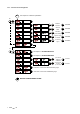
5.3 - Measurement result
After performing a balancing spin, the amounts of unbalance are shown on the digital readouts.
The illuminated LEDs 3 and 4 indicate the correct angular position of the wheel to mount the counterweights (12
o’clock).
Fig. 7A - Inside correction
Fig. 7B - Outside correction
5.4 - Recalculation of the unbalance
Automatic on varying set-up with the buttons
ALU
.
5.5 - Exact positioning of the adhesive weight by means of the gauge with clips
- press
If the unbalance is less than the threshold value selected,
is displayed instead of the unbalance value; with
<T
the values below the threshold can be read.
5.3.1 - Measurement precision
The machine uses special devices (WP) to ensure the best possible measurement speed and controlled measurement
precision less than 1 gr. Operation is automatic and the measurement is highlighted as soon as sufcient precision is
reached. In the event of excessive vibration of the oor or exceptional shock, the wheel balancer might execute the
maximum number of permissible measurements. In this case, the following symbol is displayed:
- Fit the correction weight in the specic gauge seat with the adhesive
part facing upwards
- bring the wheel into correct angular position for the plane to be
corrected
- withdraw the gauge until the correction plane indication arrows turn
green
INSIDE CORRECTION POSITION
OUTSIDE CORRECTION POSITION
- rotate the gauge until the correction weight adheres to the rim
- the fact that the weight application position is no longer vertical (Fig. 8)
is automatically compensated
- to cancel this function, press button again
N.B. : It is not possible to put automatically the correction
weight in the Fig.5/B position; always rotate the rim in
Fig.5/A upwards.
Correct the result all the same and check with a test launch.