
Instruction Manual


6
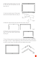
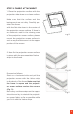
3. Place all four frame parts 2x (A) and
2x (B) into the nal position on the
oor (Fig. 3).
Fig 3
4. Insert one metal corner (E) into each
end of the horizontal frame (A) (Fig. 4).
Fig 4
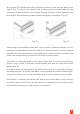
5. Slide the vertical frame parts (B) onto the corners (Fig. 5).
Fig 5
6. Slide the lower horizontal frame sec-
tion (A) onto the vertical frame parts
(B) (Fig. 6).
Fig 6
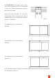
7. Once all frame parts are inserted into each other, each corner is xed with
4x screws (J) (Fig. 7). When tightening, make sure that the corners are exact-
ly at 90° to each other, Only then should you tighten the screws.
Fig 7