Operating instructions celexon Expert Frame Pure White Thank you for purchasing this product. For optimum performance and safety, please read these instructions carefully before connecting or operating this product. Please retain these instructions for future reference.
WARNINGS The purpose of these operating instructions is to familiarise you with the operation of this product. Therefore, keep these instructions in a safe place so that you can access them at any time. • Before installation, please refer to the enclosed data sheet for further safety and use instructions. • Do not begin installation until you have read and understood the complete operating instructions.
• Tighten the screws but do not overtighten them. Overtightening (e.g. by using a cordless screwdriver) this can cause damage and affect the secure hold of the screen. • Suspended loads must be checked for strength and load-bearing capacity at least twice a year. • Failure to follow the above instructions may result in personal injury and damage to the product or equipment attached to it. Incorrect installation or use may also invalidate the warranty may be voided.
DISCLAIMER The information in this document is subject to change without notice by the manufacturer. Changes will be added to subsequent versions of this manual. Errors expected. CARE INSTRUCTIONS NEVER clean the screen with alcohol or other cleaning agents containing solvents.Use only a soft and clean cloth. If necessary, dirt can be removed from the surface with a mild soap solution (max. 5%). It is essential to avoid contact with pointed or sharp objects.
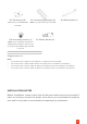
8x Slip thread (G) 2x Connecting element (H) 2 pieces per (L) are additionally Note: only required if (A) is divided 4x Wall bracket (I) in the box 24x mounting screws (J) 8x Plastic dowel (K) Note: If (A) is divided, 8 pieces are additionally included in the box, Per (L) 2 pieces are additionally included in the box Support strut (L) Note: • For screens with a width of up to 250cm, no support strut is included.
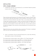
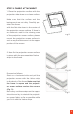
INSTALLATION STEP 1: FRAME ASSEMBLY 1. ATTENTION: This step is only necessary if (A) is divided. Otherwise, please continue with the next step. Abb. 1 Place the horizontal frame parts (A) with the flat side on the floor. Place a clean and soft cloth under the frame parts to avoid scratches on the surface. The two vertically cut sides should face each other. Place a connecting element (H) in a frame part according to figure 1. Make sure that the holes are aligned.
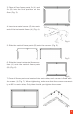
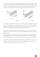
3. Place all four frame parts 2x (A) and 2x (B) into the final position on the floor (Fig. 3). 4. Insert one metal corner (E) into each Fig 3 end of the horizontal frame (A) (Fig. 4). Fig 4 5. Slide the vertical frame parts (B) onto the corners (Fig. 5). Fig 5 6. Slide the lower horizontal frame section (A) onto the vertical frame parts (B) (Fig. 6). Fig 6 7. Once all frame parts are inserted into each other, each corner is fixed with 4x screws (J) (Fig. 7).
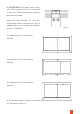
. ATTENTION: This step is only required if the support strut (L) is included in the box. Otherwise please continue with the next step. Align the slip threads (G) and the supporting braces according to Fig. 8 depending on the number of support struts (L) supplied. Fig 8 1x Support strut (L) included in delivery 2x Support strut (L) included in delivery 3x Support strut (L) included in delivery 9. Screw the support strut(s) (L) and the wall suspension (I) to the slip threads (G) with the screws (J).
STEP 2: FABRIC ATTACHMENT 1. Place the projection surface with the projection side down on a clean surface. Make sure that the surface and the background are not dirty. Carefully position the frame. with the flat side down in the centre of the projection screen surface. If there is an ultrasonic weld in the viewing area of the projection screen surface, please Fig 9 mount the projection screen surface in such a way that this seam is in the upper portion of the screen. 2.
Now place the corner strip with sufficient tension on the narrow side of the frame (Fig. 12) and fix the vertical side of the projection screen fabric to the aluminium frame with the Velcro strips. Repeat the step on the opposite side and stretch the projection screen surface as tightly as possible. (Fig. 13). Fig. 12 Fig. 13 Depending on the weather, the fabric can be hard to correctly tension.
STEP 3: WALL MOUNTING 1. Mount two wall brackets (I) per horizontal frame part (A). Make sure that the brackets are evenly distributed along the length (as shown in Fig. 14) and are opposite each other. Fig 14. 2. Measure the distance H and L (acc. to fig. 10) and transfer this onto the wall (Fig. 15). Fig 15. 3. Mount the mounting bracket (C) with the self-tapping screws (F) and the plastic dowels (K) in a load-bearing surface. Please use suitable mounting material for your surface. 4.