
Phau Ntawv Qhia

5. Resetthesensorbycommunicationcommandfromthepanel.
TESTING
Detectors must be tested after installation and following periodic main-
tenance. However, before testing, notify the proper authorities that the
smokedetectorsystemisundergoing maintenanceand thesystemwill
be temporarily out of service. Disable the zone or system undergoing
maintenancetopreventunwantedalarms.
Testthesensorsasfollows:
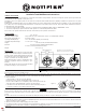
A.TestMagnet(ModelM02-04–optional)
1. Test the sensor by positioning the optional test magnet against
the sensor plastic in the magnet test area, as shown in Figure 3.
2. Both LEDs should latch on within 30 seconds,
indicatinganalarmandannunciatingthepanel.
B. SmokeEntry:AerosolGenerator(Gemini501)
The GEMINI model 501 aerosol generator can be used for
smoke entry testing. Set the generator to represent 4%/ft to 5%/
ft obscuration as described in the GEMINI 501 manual. Using the
bowlshapedapplicator,applyaerosoluntilthepanelalarms.
CLEANING
Before cleaning, notify the proper authorities that the system is under-
going maintenance and will be temporarily out of service. Disable the
systemtopreventunwantedalarms.
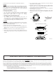
1. Removethesensortobecleanedfromthesystem.
2. Removethesensorcover,seeFigure4.Useasmallstandardscrew-
drivertoreleaseeachofthefourcoverremovaltabsthatholdthecover
inplace.
3. Vacuumtheoutsideofthescreencarefullywithoutremovingit.
4. Remove the sensor screen. Pull the screen straight away from the
sensingchamberuntilitsnapsoutofplace.Replacementscreensare
available.
N500-57-00 2 I56-1249-04R
©2001Notier
Figure3.TestMagnetPositioning
Figure4.Cleaning
A78-2463-13
SENSOR
COVER
SENSING
CHAMBER
SENSOR
SCREEN
COVERREMOVAL
TABS
PCBOARD
CONTACT
SENSOR
CONTACTS
LED2
LED1
PAINTED
SURFACE
TEST
MAGNET
MAGNET
TESTMARKER
A78-2424-10
5. Useavacuumcleanerorclean,compressedairtoremovedustand
debrisfromthesensingchamber.
6. Reinstallorreplacethesensingchamberscreenbyslidingthe edge
withoutthetabsoverthesensingchamber.Makesurethatoneofthe
screencontactstouchesthecircuitboardcontact.
7. Reinstallthesensorcover.UsetheLEDsto alignthecover withthe
sensor.Snapthecoverintoplace.
8. When all sensors have been cleaned, restore power to the system
and test the sensor(s) as described in the TESTING section of this
manual.
FCCStatement
Thisdevicecomplieswithpart15oftheFCCRules.Operationissubjecttothefollowingtwoconditions:(1)Thisdevicemaynotcauseharmfulinterference,and(2)this
devicemustacceptanyinterferencereceived,includinginterferencethatmaycauseundesiredoperation.
Note: ThisequipmenthasbeentestedandfoundtocomplywiththelimitsforaClassBdigitaldevice,pursuanttoPart15oftheFCCRules.Theselimitsaredesignedto
providereasonableprotectionagainstharmfulinterferenceinaresidentialinstallation.Thisequipmentgenerates,usesandcanradiateradiofrequencyenergyand,ifnot
installedandusedinaccordancewiththeinstructions,maycauseharmfulinterferencetoradiocommunications.However,thereisnoguaranteethatinterferencewillnot
occurinaparticularinstallation.Ifthisequipmentdoescauseharmfulinterferencetoradioortelevisionreception,whichcanbedeterminedbyturningtheequipmentoffand
on,theuserisencouragedtotrytocorrecttheinterferencebyoneormoreofthefollowingmeasures:
–Reorientorrelocatethereceivingantenna.
–Increasetheseparationbetweentheequipmentandreceiver.
–Connecttheequipmentintoanoutletonacircuitdifferentfromthattowhichthereceiverisconnected.
–Consultthedealeroranexperiencedradio/TVtechnicianforhelp.
PleaserefertoinsertfortheLimitationsofFireAlarmSystems