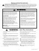
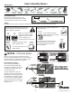
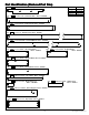
F O R E S T H I L L R E T R E AT P L AY S Y S T E M – F23180 INSTALLATION AND OPERATING INSTRUCTIONS WARNING 28'-4" To reduce the risk of serious injury or death, you must read and follow these instructions. Keep and refer to these instructions often and give them to any future owner of this play system. Manufacturer contact information provided below. 16'-4" OBSTACLE FREE SAFETY ZONE - 28’4” x 26’ area requires Protective Surfacing. See page 3. 7'-7" 26'-0" MAXIMUM VERTICAL FALL HEIGHT - 6’5” (1.
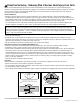
Warnings and Safe Play Instructions CONTINUOUS ADULT SUPERVISION REQUIRED. Most serious injuries and deaths on playground equipment have occurred while children were unsupervised! Our products are designed to meet mandatory and voluntary safety standards. Complying with all warnings and recommendations in these instructions will reduce the risk of serious or fatal injury to children using this play system.
Protective Surfacing - Reducing Risk of Serious Head Injury From Falls. One of the most important things you can do to reduce the likelihood of serious head injuries is to install shock-absorbing protective surfacing under and around your play equipment. The protective surfacing should be applied to a depth that is suitable for the equipment height in accordance with ASTM F1292.
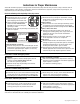
Instructions for Proper Maintenance Your Cedar Summit Play System is designed and constructed of quality materials with your child’s safety in mind. As with all outdoor products used by children, it will weather and wear. To maximize the enjoyment, safety and life of your Play Set, it is important that you, the owner, properly maintain it. Check the following at the beginning of the play season: HARDWARE: Check metal parts for rust.
About Our Wood Cedar Summit Premium Play Systems uses 100% FSC wood. Although we take great care in selecting the best quality lumber available, wood is still a product of nature and susceptible to weathering which can change the appearance of your set. What causes weathering? Does it affect the strength of my Play System? One of the main reasons for weathering is the effects of water (moisture); the moisture content of the wood at the surface is different than the interior of the wood.
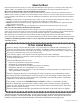
Keys to Assembly Success Tools Required Shovel Measuring Tape Drill (1/8” 3/16” Bit) Safety Glasses Hammer Part Identification Key On each page, you will find the parts and quantities required to complete the assembly step illustrated on that page. Here is a sample. Ratchet 1/2”, 7/16” & 9/16” Level #2 & #3 Phillips or Robertson Square Ruler Step Ladder 2X 1234 Post 2 x 4 x 83” Symbols Throughout these instructions symbols are provided as important reminders for proper and safe assembly.
5/16" (8mm) Flat Washer 1/4" (6mm) Lock Washer 5/16" (8mm) T-Nut 1/4" (6mm) T-Nut 1/4" (6mm) Flat Washer 5/16" (8mm) Flat Washer For example: BOLT LENGTH 4½ (4.5) inches long 1 inch = 25.4mm LENGTH CONVERSION 0.31 inches x 25.4mm = 8mm BOLT DIAMETER 5/16 (0.31) inches For example: 1 inch = 25.4mm DIAMETER CONVERSION HARDWARE LENGTH CHART inches vs millimetres 6 152 5½ 140 5 127 114 4½ 4 102 3½ 89 3 76 2½ 64 2 51 1½ 38 1¼ 32 1-1/8 29 1 25.4 7/8 22 3/4 19 1/2 12.
63.5 2 1/2" 5/4 x 3 88.9 3 1/2" 5/4 x 4 114.3 4 1/2" 5/4 x 5 139.7 5 1/2" 5/4 x 6 88.9 3 1/2" 4x4 38.1 1 1/2" 34.9 1 3/8" 34.9 1 3/8" 38.1 1 1/2" 38.1 1 1/2" 2x6 136.5 5 3/8" 2x4 85.7 3 3/8" 2x3 63.5 2 1/2" 2 x2 15.9 5/8" 82.6 3 1/4" 34.9 1 3/8" 60.3 2 3/8" 85.7 3 3/8" 114.3 4 1/2" 136.5 5 3/8" 1/2 x 4 1x2 1x3 1x4 1x5 1x6 LENGTH CONVERSION 1 inch = 25.4mm 59.25 inches x 25.4mm = 1505mm For example: BOARD LENGTH 59¼ (59.25) inches 15.9 5/8" 15.9 5/8" 15.9 5/8" 15.
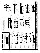
Part Identification (Reduced Part Size) 6pc. - 1930 - 3/8 x 3-1/2 x 41-1/2" - Siding - Box 2 - 3631930 Nominal Size 12pc. - 1482 - - Siding 3/8 x 3-1/2 x 42-5/8" - Box 2 - 3631482 Actual Size 3/8 x 3-1/2 3/8 x 3-1/2 1x2 5/8 x 1-3/8 1 x 2-1/2 5/8 x 1-3/4 1x4 5/8 x 3-3/8 1x5 5/8 x 4-1/2 24pc. - 5155 - 3/8 x 3-1/2 x 47-1/2" - Cedar Roofing - Box 2 - 3635155 2pc. - 1419 - - Window Divider 1 x 2 x 10-3/4" - Box 2 - 3631419 4pc. - 1433 - - Gable Board B 1 x 2 x 14" - Box 2 - 3631433 4pc.
Part Identification (Reduced Part Size) 1pc. - 1438 - 1 x 5 x 34-1/4" - Crowsnest Gap - Box 4 - 3631438 1pc. - 1406 - 1 x 5 x 41-1/2" - Ground SL Side - Box 3 - 3641406 Nominal Size Actual Size 1x5 1x6 5/4 x 3 5/8 x 4-1/4 5/8 x 5-1/4 15/16 x 2-1/2 5/4 x 4 15/16 x 3-1/2 1pc. - 2584 - 1 x 5 x 45-1/2" - Front Ground - Box 3 - 3632584 1pc. - 2585 - 1 x 5 x 77" - Back Ground - Box 2 - 3632585 1pc. - 2598 - 1 x 5 x 85-61/64" - Ground SW Side - Box 3 - 3632598 5pc.
Part Identification (Reduced Part Size) 2pc. - 2592 - 5/4 x 4 x 32" - Bench Top - Box 4 - 3632592 2pc. - 0522 - 5/4 x 2 x 8" - Window Dormer Cleat - Box 2 - 3630522 2pc. - 1443 - 5/4 x 3 x 18" - Crowsnest Side - Box 4 - 3641443 Nominal Size Actual Size 5/4 x 4 15/16 x 3-1/4 5/4 x 2 1 x 1-3/8 5/4 x 3 1 x 2-1/2 5/4 x 4 1 x 3-1/2 5/4 x 5 1 x 4-1/2 5/4 x 6 1 x 5-1/2 1pc. - 1448 - 5/4 x 3 x 25-1/4" - Crowsnest Short - Box 3 - 3641448 6pc. - 1423 - 5/4 x 3 x 32" - Picket - Box 3 - 3641423 2pc.
Part Identification (Reduced Part Size) 1pc. - 0437 - 5/4 x 6 x 41-1/2" - SW Floor - Box 3 - 3640437 Nominal Size Actual Size 1pc. - 2589 - 5/4 x 6 x 45-1/2" - Table Top - Box 3 - 3632589 5/4 x 6 1 x 5-1/2 2x3 1-1/4 x 2-1/4 2x4 1-1/4 x 3-1/4 2x3 1-3/8 x 2-1/2 2x4 1-3/8 x 3-3/8 2pc. - 2590 - 5/4 x 6 x 45-1/2" - Top Back Front - Box 3 - 3632590 1pc. - 2491 - 2 x 3 x 42-1/4" - Diagonal - Box 4 - 3632491 1pc. - 2484 - 2 x 4 x 13-1/2" - Bench Leg - Box 3 - 3632484 2pc.
Part Identification (Reduced Part Size) Nominal Size Actual Size 1pc. - 2025 - 2 x 4 x 38" - Wall Mount - Box 2 - 3642025 2x4 1-3/8 x 3-3/8 2x6 1-1/2 x 5-3/8 2x2 1-1/2 x 1-1/2 1pc. - 0834 - 2 x 4 x 41-1/2" - SL Floor - Box 2 - 3640834 2pc. - 2586 - 2 x 4 x 45-1/4" - Floor Front Back - Box 4 - 3632586 1pc. - 1856 - 2 x 4 x 48-5/16" - SW Upright - Box 2 - 3641856 4pc. - 1401 - 2 x 4 x 54" - Lower Post - Box 4 - 3641401 1pc. - 2600 - 2 x 4 x 62-7/8" - Left Access Rail - Box 4 - 3632600 1pc.
Part Identification (Reduced Part Size) Nominal Size Actual Size 2pc. - 1425 - 2 x 2 x 38-3/4" - Roof Joist - Box 3 - 3641425 1-1/4 x 1-1/2 1-1/4 x 1-1/2 1pc. - 1413 - 2 x 2 x 45-1/2" - Table Support - Box 3 - 3641413 2x2 1-1/2 x 1-1/2 2x6 1-1/2 x 5-3/8 1pc. - 1825 - 2 x 6 x 83-5/8" - Back Beam - Box 2 - 3631825 1pc. - 1826 - 2 x 6 x 83-5/8" - Front Beam - Box 2 - 3631826 2pc. - 0521 - Window Dormer Roof Left - Box 4 - 3630521 2pc. - 0520 - Window Dormer Roof Right - Box 4 - 3630520 6pc.
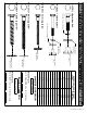
Hardware Identification (Actual Size) 11pc. LS1 - Lag Screw 1/4 x 1-1/2" - (9262212) 7pc. LS3 - Lag Screw 1/4 x 3" - (9262230) 2pc. H2 - Hex Bolt 1/4 x 2" - (9277220) 15pc. H10 - Hex Bolt 1/4 x 2-1/4" - (9277221) 4pc. H11 - Hex Bolt 1/4 x 2-3/4" - (9277223) 10pc. H13 - Hex Bolt 1/4 x 3-1/2" - (9277232) 8pc. H4 - Hex Bolt 1/4 x 4" - (9277240) 7pc. H8 - Hex Bolt 1/4 x 4-1/4" - (9277241) 6pc. H6 - Hex Bolt 1/4 x 4-3/4" - (9277243) 1pc. H14 - Hex Bolt 1/4 x 5" - (9277250) 4pc.
Hardware Identification (Actual Size) 16pc. LW2 - 5/16" Lock Washer - (9253300) 69pc. LW1 - 1/4" Lock Washer - (9253200) 12pc. FW0 - 3/16" Flat Washer - (9251100) 59pc. TN1 - 1/4" T - Nut -(9285200) 76pc. FW1 - 1/4" Flat Washer - (9251200) 16pc. TN2 - 5/16" T- Nut - (9285300) 12pc. LN2 - 5/16" Lock Nut - (9283300) 40pc. FW2 - 5/16" Flat Washer - (9251300) 10pc. BN1 - 1/4" Barrel Nut - (9248200) 2pc. LN4 - #12 Nylok Nut - (9289600) 89pc. LN1 - 1/4 Lock Nut - (9283200) 51pc.
Part Identification (Reduced Part Size) 1x - Flower Box (9320401) Green 1x - Cedar Summit ID Plaque (9320357) 1x - TNR 2 Post Mount (9200203) 2x.
Step 1: Inventory Parts - Read This Before Starting Assembly STOP A. STOP STOP STOP his is the time for you to inventory all your hardware, wood and accessories, T referencing the parts identification sheets. This will assist you with your assembly. • The wood pieces will have the four digit key number stamped on the ends of the boards. The wood pieces are referenced throughout the instructions with this number. • Please refer to Page 6 for proper hardware assembly.
Step 2: Access Ladder / Rockwall Assembly Part 1 A: Place (2600) Left Access Rail on left hand side of 4 (8517) Ladder Treads and (2251) Right Rail on right hand side with the grooves facing in. (fig. 2.1) B: Fit each (8517) Ladder Tread into grooves on both (2600) Left Access Rail and (2251) Right Rail, make sure the top edge of the treads are flush to the front of the rails. (fig. 2.1 and 2.
Step 2: Access Ladder / Rockwall Assembly Part 2 E: Place (8514) Gap Ladder on each rail so there is a 2-3/8” gap between (8514) Gap Ladder and the top (8517) Ladder Tread. Attach using 4 (S3) #8 x 2-1/2” Wood Screws. (fig. 2.4 and 2.5) F: Place (2252) Rock Rail on the ground next to (2251) Right Rail so it matches the orientation of the two rails as shown in fig. 2.6. Attach (2596) Top Ladder to top of Access Ladder assembly and (2252) Rock Rail using 3 (S3) #8 x 2-1/2” Wood Screws.
Step 3: Rockwall Assembly Part 1 A: Place (2597) Rock Top at top of the Access Ladder/Rockwall Assembly and (0606) CE Access Board at the bottom of the assembly as shown in fig. 3.1. Then place (0630) CE Rock Board and (0631) CE Rock Board as shown in fig. 3.1. Do not screw boards down yet. Rock holes are to be staggered so they do not form a straight line and are at the top of the boards. Note: Rock Boards are to be flush to (2251) Right Rail and pilot holes are centred over (2252) Rock Rail. (fig. 3.
Step 3: Rockwall Assembly Part 2 D: Alternating colours and shapes, attach 1 rock to each rock board using 1 (PB2) 1/4 x 1-1/4” Pan Bolt (with lock washer, flat washer and barrel nut) and 1 (S10) #8 x 1” Pan Screw per rock. (fig. 3.2 and 3.3) The Pan Screw is placed in the hole beneath the Pan Bolt. (fig. 3.2 and 3.3) Note: Make sure all hardware is used to secure each rock properly. Fig. 3.2 3/16” Flat Washer 1/4” Lock Washer Fig. 3.
Step 4: Swing Beam Assembly WARNING: Fig. 4.4 A: In the middle holes of (1825) Back Beam install 2 Bolt-Thru Swing Hangers (fig. 4.1) making sure the swing hangers are oriented in the direction shown in fig. 4.4 to maintain proper swing motion. For your child’s safety, orientate the swing hangers as shown to ensure your swing will have proper swing motion when installed. Failure to do so could result in premature failure of the swing hanger or swing chain.
Step 5: Swing End Assembly A: Attach 2 (1863) SW Posts to (1856) SW Upright using 2 (G4) 5/16 x 4” Hex Bolts (with lock washer, flat washer and t-nut). (fig. 5.1) G5 Fig. 5.1 5/16” Lock Washer 1863 1856 5/16” Flat Washer 5/16” T-Nut 5/16” T-Nut 5/16” Lock Washer 5/16” Flat Washer G4 1862 1863 B: Attach (1862) SW Support to both (1863) SW Posts and (1856) SW Upright using 3 (G5) 5/16 x 4-1/2” Hex Bolts (with lock washer, flat washer and t-nut). (fig. 5.
Step 6: Attach Swing End to Swing Beam A: Place (4919) SW Rail Block in the centre between (1826) Front Beam and (1825) Back Beam and attach with 1 (H8) 1/4 x 4-1/4” Hex Bolt (with lock washer, flat washer and t-nut). (fig. 6.1 and 6.2) Fig. 6.1 Fig. 6.2 H8 Glider Hangers 1/4” Lock Washer WARNING: 1/4” Flat Washer 1826 Glider Hangers must be tight and secure to Swing Beams. 4919 1/4” T-Nut 1825 B: Attach Swing End Assembly to the side of the Swing Beam Assembly with the overhang (fig. 6.
Step 7: Small Dormer Assembly A: Insert 2 sides from the Small Window Dormer Set into the front of the dormer as shown in fig. 7.1. B: Attach (0520) Window Dormer Roof Right and (0521) Window Dormer Roof Left together with Window Dormer Bracket and 2 (S5) #8 x 1/2” Pan Screws. (fig. 7.2) C: Attach Small Window Dormer Set Assembly to (0520) Window Dormer Roof Right and (0521) Window Dormer Left with 6 (S5) #8 x 1/2” Pan Screws. (fig. 7.2) D: Repeat to create a second Small Window Dormer Assembly. Fig.
Step 8: Roof Assembly Part 1 A: Connect 2 (1424) Roof Supports together at the peak using 1 (S4) #8 x 3” Wood Screw. Repeat this to create 2 Roof Support Assemblies. Make sure the supports are tight to each other. (fig. 8.1) B: Connect 2 (1425) Roof Joists together at the peak using 1 (S4) #8 x 3” Wood Screw. Make sure the joists are tight to each other. (fig. 8.1) C: Place each Roof Support Assembly so the side with the ledge faces in. The Roof Joist Assembly should be in the middle.
Step 8: Roof Assembly Part 2 D: At the peak attach 1 (5155) Cedar Roofing per side to both Roof Support Assemblies and the Roof Joist Assembly using 3 (S0) #8 x 7/8” Truss Screws per roofing. (fig. 8.2) One (5155) Cedar Roofing should overlap the other. (fig. 8.3) E: At the bottom of the the Support and Joist Assemblies pre-drill 1” above the existing holes in (5155) Cedar Roofing and then attach to each side with 3 (S0) #8 x 7/8” Truss Screws per roofing. (fig. 8.
Step 8: Roof Assembly Part 3 F: On one side, starting at the bottom and working up, attach 10 (5155) Cedar Roofing to both Roof Support Assemblies and the Roof Joist Assembly with 3 (S0) #8 x 7/8” Truss Screws per roofing. Make sure that one roofing overlaps the other. (fig. 8.5 and 8.6) G: On the other side, starting at the bottom and working up attach 7 (5155) Cedar Roofing to both Roof Support Assemblies and the Roof Joist Assembly with 3 (S0) #8 x 7/8” Truss Screws per roofing.
Step 8: Roof Assembly Part 4 H: On the side of the Roof Assembly with 9 (5155) Cedar Roofing, on the 4th roofing, 8” in from the edge of each side, attach 2 (0522) Window Dormer Cleats with 1 (S6) #12 x 1” Pan Screw (with 3/16” flat washer) per cleat. Screws are to be installed from the underside of the roof. (fig. 8.7) I: Hang both Small Dormer Assemblies, from Step 7, by the Window Dormer Bracket on the 8th (5155) Cedar Roofing. Make sure the dormer assemblies cover the (0522) Window Dormer Cleats.
Step 8: Roof Assembly Part 5 L: Place (1434) Roof Side flush to the bottom edges of 1 Roof Support Assembly and attach with 1 (S4) #8 x 3” Wood Screw and 1 (S3) #8 x 2-1/2” Wood Screw on each end as shown in fig. 8.9 and 8.10. M: Place (2595) Side Roof flush to the bottom edges of the remaining Roof Support Assembly and attach with 1 (S4) #8 x 3” Wood Screw and 1 (S3) #8 x 2-1/2” Wood Screw on each end as shown in fig. 8.9 and 8.10. Fig. 8.9 1424 1434 1424 2595 1424 1434 1424 Fig. 8.
Step 9: Post Assembly A: Place 1 (1400) Post beside 1 (1401) Lower Post making sure the 3 holes in (1400) Post are at the top of the boards and facing the front as shown in fig. 9.1. B: To align holes properly, insert a bolt through the bottom holes of (1400) Post and (1401) Lower Post as shown in fig. 9.2. Once boards are aligned properly, attach together with 7 (S3) #8 x 2-1/2” Wood Screws and then remove the bolt. (fig. 9.1) C: Repeat these steps 3 more times to create 4 Post Assemblies in total.
Step 10: Swing Wall Assembly Part 1 A: Attach (2598) Ground SW Side to 2 Post Assemblies with 2 (H4) 1/4 x 4” Hex Bolts (with lock washer, flat washer and t-nut) as shown in fig. 10.1. Notice how the board is placed. Keep the bolts loose. B: Attach (0437) SW Floor to each (1400) Post, in the bottom holes, with 2 (H8) 1/4 x 4-1/4” Hex Bolts (with lock washer, flat washer and t-nut) and (0436) SW Top using 4 (H8) 1/4 x 4-1/4” Hex Bolts (with lock washer, flat washer and t-nut). (fig. 10.
Step 10: Swing Wall Assembly Part 2 Note: Pre-drill all holes using a 1/8” drill bit before installing the Lag Screws. D: Make sure the assembly is square and then attach (0437) SW Floor to both (1400) Posts in the top holes using 2 (LS3) 1/4 x 3” Lag Screws (with flat washer) and (2598) Ground SW Side to each (1401) Lower Post with 2 (H4) 1/4 x 4”” Hex Bolt (with lock washer, flat washer and t-nut). (fig. 10.
Step 11: Slide Wall Assembly A: Attach (1406) Ground SL Side to the remaining 2 Post Assemblies with 4 (H4) 1/4 x 4” Hex Bolts (with lock washer, flat washer and t-nut) as shown in fig. 11.1. Keep bolts loose. B: Attach (0834) SL Floor to each (1400) Post with 2 (H6) 1/4 x 4-3/4” Hex Bolts (with lock washer, flat washer and t-nut). (fig. 11.1) Keep bolts loose. C: Tight to the bottom of (0834) SL Floor attach (2599) SL Spacer to each (1400) Post with 4 (S3) #8 x 2-1/2” Wood Screws. (fig. 11.
Step 12: Front and Back Frame Assembly Keep all bolts in this step loose until a later step. A: Attach 1 (2586) Floor Front Back to the inside of each Post Assembly on both the Swing Wall and Slide Wall Sides using 1 (H11) 1/4 x 2-3/4” Hex Bolt (with lock washer, flat washer and t-nut) per corner. Bolts are installed from the inside of the fort. Notice that the holes on (2586) Floor Front Back are towards the bottom of the boards. (fig. 12.
Step 13: Front Frame Assembly Part 1 A: Remove the bottom bolt in (2025) Wall Mount. Do not discard this bolt you will re-install it after the (2587) Floor Joist is attached. (fig. 13.2) B: From the inside of the assembly measure 1-13/16” down from the top of (0437) SW Floor and then attach (2587) Floor Joist with 2 (S4) #8 x 3” Wood Screws. (fig. 13.1, 13.2 & 13.3) C: Attach the other side of (2587) Floor Joist flush to the top of (0834) SL Floor with 2 (S4) #8 x 3” Wood Screws. (fig. 13.
Step 13: Front Frame Assembly Part 2 E: Attach (0839) CE Gap Board to each (2586) Floor Front Back and (2587) Floor Joist on the the Swing Wall Side using 5 (S2) #8 x 1-1/2” Wood Screws. (fig. 13.4 and 13.5) F: Flush to the the outide face of (0834) SL Floor attach 1 (0840) CE Gap Board to each (2586) Floor Front Back, (0834) SL Floor and (2587) Floor Joist using 5 (S2) #8 x 1-1/2” Wood Screws. (fig. 13.4 and 13.5) Fig. 13.
Step 13: Front Frame Assembly Part 3 G: In between both (0839) CE Gap Board and (0840) CE Gap Board place 11 (0839) CE Gap Boards making sure they are evenly spaced. Attach to (2587) Floor Joist and both (2586) Floor Front Back using 5 (S2) #8 x 1-1/2” Wood Screws per board. (fig. 13.6) Fig. 13.6 S2 x 5 per board 0839 2586 (hidden) 2586 2587 (hidden) 0840 0839 x 11 Wood Parts 11 x 0839 CE Gap Board 1 x 4 x 38-3/4” Hardware 55 x S2 #8 x 1-1/2” Wood Screw 39 support@cedarsummitplay.
Step 14: Attach Floor Gap A: On the Front Wall in between (1400) Posts and flush to the top of the (0839) CE Gap Boards attach (2588) Floor Gap to (2586) Floor Front Back with 4 (S3) #8 x 2-1/2” Wood Screws. (fig. 14.1 and 14.2). Fig. 14.1 Fig. 14.2 1400 2586 (hidden) 0839 Front Wall Flush 1400 S3 2588 Front Wall Wood Parts 1x 2588 Floor Gap 2 x 3 x 38-5/8” Hardware 4x S3 #8 x 2-1/2” Wood Screw 40 support@cedarsummitplay.
Step 15: Top Frame Assembly Part 1 A: From outside the fort attach a 1/4” t-nut in the middle hole of each (1400) Post on the Slide Wall as shown in fig. 15.1 and 15.2. B: Attach 1 (2590) Top Back Front to each (1400) Post on the Front and Back Walls with 4 (H10) 1/4 x 2-1/4” Hex Bolts (with lock washer, flat washer and t-nut) per board. (fig. 15.1 and 15.2) 2590 Fig. 15.1 2590 1400 Fig. 15.
Step 15: Top Frame Assembly Part 2 C: Place 1 (1404) Roof Block tight to the top of each (1400) Post on the Slide Wall, the bevelled edge to be at the top. On the inside of the assembly place 1 (2594) SL Post Support flush to the top of (1404) Roof Block and attach to (1400) Posts and (1404) Roof Block with 9 (S3) #8 x 2-1/2” Wood Screws per support. (fig. 15.3 and 15.4) D: Place 1 (1404) Roof Block tight to the top of each (1400) Post on the Swing Wall, the bevelled edge to be at the top.
Step 16: Front Window Wall Assembly Part 1 A: Tight to the top (2590) Top Back Front on the Front Wall and 1-3/8” from the outside edge of each (1404) Roof Block attach (1412) Window Sill to (1404) Roof Blocks with 4 (S2) #8 x 1-1/2” Wood Screws. (fig. 16.1 and 16.2) B: Tight to the bottom of (2590) Top Back Front attach 1 (1411) Wall Trim flush to the outside edge of each (1400) Post with 4 (S2) #8 x 1-1/2” Wood Screws per board. (fig. 16.1 and 16.
Step 16: Front Window Wall Assembly Part 2 D: On the inside of the assembly centre 2 (1417) Window Braces over the pilot holes in (1412) Window Sill and then attach to (1412) Window Sill from the outside of the assembly using 1 (S2) #8 x 1-1/2” Wood Screws per brace. (fig. 16.3 and 16.4) E: Attach 5 more (1482) Siding directly above the first and attach to (1400) Posts and (1417) Window Braces with 4 (S0) #8 x 7/8” Truss Screws per board. (fig. 16.3 and 16.4) Fig. 16.3 Fig. 16.
Step 16: Front Window Wall Assembly Part 3 F: Loosen bolts in (2590) Top Front Back then from the inside of the assembly, place 1 Window Mesh against (2590) Top Back Front, there will be a small gap above (1482) Siding. Attach to (2590) Top Back Front with 8 evenly spaced (S5) #8 x 1/2” Pan Screws (with #8 flat washer) as shown in fig. 16.5 and 16.6, make sure the mesh is tucked in and then retighten bolts.
Step 16: Front Window Wall Assembly Part 4 H: On the outside of the assembly, tight to the top of (1482) Siding, attach 1 (1412) Window Sill to (1400) Posts and (1417) Window Braces with 6 (S2) #8 x 1-1/2” Wood Screws. Make sure the mesh is smooth and tight. (fig. 16.8 and 16.9) I: Attach the bottoms of Window Mesh to (1412) Window Sill from the inside of the assembly with 8 (S5) #8 x 1/2” Pan Screws (with #8 flat washer). Make sure the mesh is smooth and tight. (fig. 16.
Step 17: Attach Flower Box A: In the centre and top of the lower (1412) Window Sill attach Flower Box with 2 (S5) #8 x 1/2” Pan Screw. (fig. 17.1 and 17.2) Fig. 17.1 1412 Fig. 17.2 S5 1412 Flower Box Hardware 2x S5 #8 x 1/2” Pan Screws 47 Other Parts 1 x Flower Box support@cedarsummitplay.
Step 18: Attach Pickets to Swing Wall A: Starting at 1 (2593) Post Support on the Swing Wall measure 3” then place 1 (1423) Picket, with bevelled edges to the top and facing out and tight to (0839) CE Gap Board, then attach to (0436) SW Top and (0437) SW Floor with 2 (S15) #8 x 1-3/4” Wood Screws. Follow with 2 more (1423) Pickets, each 3” apart. Repeat starting at the other (2593) Post Support. (fig. 18.1 and 18.2) Fig. 18.1 Swing Wall Note: Gaps between boards not to exceed 3-1/4” Fig. 18.
Step 19: Attach Window Sill to Back Wall A: Tight to the top (2590) Top Back Front on the Back Wall and 1-3/8” from the outside edge of each (1404) Roof Block attach (1412) Window Sill to (1404) Roof Blocks with 4 (S2) #8 x 1-1/2” Wood Screws. (fig. 19.1 and 19.2) Fig. 19.1 1404 1404 Fig. 19.2 1-3/8” 1404 Back Wall 1412 S2 2590 Wood Parts 1x 1412 Window Sill 1 x 4 x 42-5/8” x4 Hardware 4x S2 #8 x 1-1/2” Wood Screw 49 support@cedarsummitplay.
Step 20: Attach Roof to Fort A: With at least 2 helpers lift roof onto fort at Slide Wall side of the fort. (1434) Roof Side should be on the Slide Wall and (2595) Side Roof Should be on the Swing Wall. Dormer Windows should be on the Front Wall. (fig. 20.1) B: Attach (1434) Roof Side and (2595) Side Roof to (1404) Roof Blocks with 1 (H6) 1/4 x 4-3/4” Hex Bolt (with lock washer, flat washer and t-nut) per corner. (fig. 20.1 and 20.2) Fig. 20.
Step 21: Attach Gable Boards and Tarp Part 1 A: With the assistance from a helper, from the inside of the Roof Assembly attach (1431) Centre Gable Board to the peak of the Roof Support Assembly; centre on (1430) Sunburst and (1434) Roof Side with 3 (S2) #8 x 1-1/2” Wood Screws. Make sure (1430) Sunburst is centred lengthwise on (1434) Roof Side. The end with the single hole is towards the top of the board. (fig. 21.1 and 21.
Step 21: Attach Gable Boards and Tarp Part 2 E: From the inside of the assembly attach the Tarp to each (1424) Roof Support and to (1434) Roof Side with 11 (S5) #8 x 1/2” Pan Screws (with #8 flat washer). Make sure the tarp is smooth and tight before fastening. (fig. 21.3 and 21.4) F: Repeat Step E for Back Wall and (2595) Side Roof. (fig. 21.3 and 21.4) Tarp Fig. 21.3 1424 1434 1424 Tarp Fig. 21.
Step 22: Attach Ground Stakes MOVE FORT TO FINAL LOCATION. FINAL LOCATION MUST BE LEVEL GROUND. WARNING: To prevent tipping and avoid potential injury, stakes must be driven 10-1/2” into ground. Digging or driving stakes can be dangerous if you do not check first for underground wiring, cables or gas lines. A: Drive 2 (0318) Ground Stakes 10-1/2” into the ground tight to 2 (1400) Posts as shown in fig. 22.1. Attach using 2 (S3) #8 x 2-1/2” Wood Screws per ground stake. (fig. 22.2) Fig. 22.1 Fig.
Step 23: Lower Slide Wall Assembly Part 1 Note: Pre-drill all holes using a 1/8” drill bit before installing the Lag Screws. A: Tight to the top of (1406) Ground SL Side and flush to the outside edges of both (1400) Posts on the Slide Wall side attach 6 (1930) Siding to each post with 2 (S0) #8 x 7/8” Truss Screws per board, as shown in fig. 23.1 and 23.2. Make sure there are no gaps between boards.
Step 23: Lower Slide Wall Assembly Part 2 C: From inside the assembly place 1 (1858) Short Wall Support over the pilot holes of the (1930) Siding, the top should be flush to the top of (0968) Middle Top then attach to (1406) Ground SL Side and (0968) Middle Top with 4 (S1) #8 x 1-1/8” Wood Screws per board. (fig. 23.4) D: From outside of the assembly attach (1858) Short Wall Support to each (1930) Siding with 1 (S0) #8 x 7/8” Truss Screws per siding. (fig. 23.3 and 23.5) Flush Fig. 23.3 0968 Fig. 23.
Step 24: Lower Front Wall Assembly Part 1 A: Flush to the outside edge of (1400) Post and tight to the top of (2584) Front Ground attach (1870) Trim Short to (1400) Post with 3 (S2) #8 x 1-1/2” Wood Screws. (fig. 24.1 and 24.2) B: Tight to top of (2584) Front Ground and tight to (1870) Trim Short attach 6 (1482) Siding to both (1400) Posts with 2 (S0) #8 x 7/8” Truss Screws per board. Make sure there are no gaps between boards. (fig. 24.1 and 24.
Step 24: Lower Front Wall Assembly Part 2 D: Place (1413) Table Support flush to the notched out extension of (2589) Table Top, as shown in fig. 24.5. then attach using 5 (S7) #12 x 2” Pan Screws. E: Place Table Top Assembly tight to the top of (1930) Siding, (1415) Lower Trim and (1870) Trim Short. Make sure (1413) Table Support is flush to the outside edges of both (1400) Posts then attach (1413) Table Support to each post with 2 (S3) #8 x 2-1/2” Wood Screws. (fig. 24.4 and 24.
Step 24: Lower Front Wall Assembly Part 3 G: From inside the assembly tight to the bottom of (2589) Table Top place 2 (1858) Short Wall Supports over the pilot holes of the (1482) Siding then attach to (1413) Table Support and (2584) Front Ground with 4 (S1) #8 x 1-1/8” Wood Screws per board. (fig. 24.8 and 24.9) H: From outside of the assembly attach (1858) Short Wall Supports to each (1482) Siding with 2 (S0) #8 x 7/8” Truss Screws per siding. (fig. 24.9) Fig. 24.
Step 25: Lower Swing Wall Assembly Note: Pre-drill all holes using a 1/8” drill bit before installing the Lag Screws. A: Flush to outside edges of both (1400) Posts and flush to the top of (2589) Table Top place and make sure (0968) Middle Top is level then attach to posts with 2 (LS1) 1/4 x 1-1/2” Lag Screws. (fig. 25.1 and 25.2) Fig. 25.1 1400 Fig. 25.
Step 26: Bench Assembly Part 1 Note: Pre-drill all holes using a 1/8” drill bit before installing the Screws. A: Place (0398) Bench Brace Top centred under 2 (2592) Bench Tops and attach with 4 (S15) #8 x 1-3/4” Wood Screws, as shown in fig. 26.1. B: Flush to the top of (2484) Bench Leg place (2578) Seat End, angled corner facing down. Attach with 1 (H10) 1/4 x 2-1/4” Hex Bolt (with lock washer, flat washer and t-nut).
Step 26: Bench Assembly Part 2 Note: Pre-drill all holes using a 1/8” drill bit before installing the Screws. D: Attach 1 (2578) Seat End to (2491) Diagonal with 1 (H10) 1/4 x 2-1/4” Hex Bolt (with lock washer, flat washer and t-nut). Make sure it is level then attach with 1 (S15) #8 x 1-3/4” Wood Screw. (fig. 26.3 and 26.
Step 26: Bench Assembly Part 3 F: Attach 2 Corner Brackets to (2584) Front Ground and (2591) Bench Support using 2 (S5) #8 x 1/2” Pan Screws per bracket. Corner Bracket on the inside to be flush to the top of (2591) Bench Support and Corner Bracket on the outside to be flush to the bottom of (2584) Front Ground. (fig. 26.6 and 26.7) G: Attach (2591) Bench Support to (2484) Bench Leg with 1 (S15) #8 x 1-3/4” Wood Screw. (fig. 26.
Step 27: Attach Access Ladder Rockwall Assembly Pre-drill all holes using a 1/8” drill bit before installing the Lag Screws. A: Place the Access Ladder Rockwall from Step 3 on the Back Wall, tight to (1400) Post on the Swing Wall side then attach to (2586) Floor Front Back with 1 (LS1) 1/4 x 1-1/2” Lag Screw (with flat washer) in each Swing Bracket. (fig. 27.1 and 27.
Step 28: Attach Hand Grip Pre-drill all holes using a 3/16” drill bit before installing the Lag Screws. A: On the Back Wall measure 5-1/2” up each (1400) Post from the top of floor boards then attach 1 Hand Grip with on each (1400) post with 2 (LS1) 1/4 x 1-1/2” Lag Screws (with flat washer) per Hand Grip. (fig. 28.1) 1400 Fig. 28.
Step 29: Attach SL Spacer to Back Wall A: On the Back Wall, tight to the edge of the Swing Bracket and flush to the bottom of (2586) Floor Front Back attach 1 (2599) SL Spacer to (2586) Floor Front Back with 2 (S3) #8 x 2-1/2” Wood Screws and to the inside of (2590) Top Back Front with 2 (S15) #8 x 1-3/4” Wood Screws. (fig. 29.1 and 29.2) Fig. 29.1 Fig. 29.
Step 30: Attach Swing Assembly to Fort A: Attach Swing Assembly from Step 6 to (2025) Wall Mount with 1 (G5) 5/16 x 4-1/2” Hex Bolt (with lock washer, flat washer and t-nut) and 1 (G8) 5/16 x 2” Hex Bolt (with 2 flat washers and 1 lock nut) as shown in fig. 30.1 and 30.2. B: Drive 1 (0318) Ground Stake 10-1/2” into the ground at each (1863) SW Post and attach with 2 (S3) #8 x 2-1/2” Wood Screws per ground stake. (fig. 30.1 and 30.3) 2025 5/16” T- Nut Fig. 30.1 5/16” Flat Washer 5/16” Lock Washer Fig.
Step 31: Cafe Canopy Assembly Part 1 A: Feed all canopy frames through the pockets of the canopy. (fig. 31.1) B: Place the frames together so the U-Frame is inside, then the Z-Frame and lastly the P-Frame on the outside and then attach with 1 (MB1) #12 x 1/2” Machine Bolt (with #12 lock nut) per side. (fig. 31.2 & 31.3) Fig. 31.1 Z-Frame P-Frame U-Frame Fig. 31.2 Z P Canopy removed for clarity U Fig. 31.
Step 31: Cafe Canopy Assembly Part 2 C: At the front of the fort, attach 2 Z-Frames to the (1400) Post with 1 (S6) #12 x 1” Pan Screw per frame. (fig. 31.4 and 31.5) D: From underneath the fort, attach canopy to (2588) Floor Gap with 5 (S5) #8 x 1/2” Pan Screws (with #8 flat washer). (fig. 31.6) E: Attach each P-Frame to (1400) Posts, through the tarp, with 1 (S6) #12 x 1” Pan Screw and 2 (S5) #8 x 1/2” Pan Screw (with #8 flat washer) per side. (fig. 31.6) 2588 Fig. 31.4 Fig. 31.
Step 32: Crowsnest Assembly Part 1 A: Attach 4 (1441) Crowsnest Joists to (1439) Crowsnest Front with 4 (S4) #8 x 3” Wood Screws per joist and to (1440) Crowsnest Back with 4 (S3) #8 x 2-1/2” Wood Screws per joist as shown in fig. 32.1. Fig. 32.
Step 32: Crowsnest Assembly Part 2 B: Attach (1444) Crowsnest SL Top to 2 (1447) Crowsnest Uprights using 2 (H10) 1/4 x 2-1/4” Hex Bolts (with lock washer, flat washer and t-nut), making sure the notched ends are facing out. (fig. 32.1) C: Attach 1 (1448) Crowsnest Short to (1444) Crowsnest SL Top using 6 (S15) #8 x 1-3/4” Wood Screws as shown in fig. 32.2. 1/4” T-Nut 1444 1/4” Flat Washer 1/4” Lock Washer Fig. 32.2 H10 1447 S15 Notice notched out ends x6 Fig. 32.
Step 32: Crowsnest Assembly Part 3 D: Attach 1 (1442) Crowsnest Bottom Side tight to top of (0840) CE Gap Board and flush to the inside edge of each (2594) SL Post Support using 3 (S3) #8 x 2-1/2” Wood Screws per side. Notice pilot holes towards bottom of boards. (fig. 32.4 and 32.5) E: Attach 1 (1443) Crowsnest Side to each (2594) SL Post Support using 1 (H13) 1/4 x 3-1/2” Hex Bolt (with lock washer, flat washer and previously installed t-nut) per side. (fig. 32.4 and 32.5) Fig. 32.4 Fig. 32.
Step 32: Crowsnest Assembly Part 4 F: Place assembly from Step A flush to the bottom of each (1442) Crowsnest Bottom Side then attach using 3 (S7) #12 x 2” Pan Screws per side. (1439) Crowsnest Front is to face out and (1440) Crowsnest Back is to face towards the fort. (fig. 32.6 and 32.7) G: Place assembly from Steps B and C against (1439) Crowsnest Front and attach each (1447) Crowsnest Upright to (1439) Crowsnest Front using 2 (H10) 1/4 x 2-1/4” Hex Bolts (with lock washer, flat washer and t-nut).
Step 33: Crowsnest Floor and Wall Assemblies Part 1 A: Lay down (1438) Crowsnest Gap flush to front of (1439) Crowsnest Front and (1436) Crowsnest Floor flush to back of (1440) Crowsnest Back. In between (1438) Crowsnest Gap and (1436) Crowsnest Floor place 2 (1437) Crowsnest Floors. (fig. 33.1 and 33.2) B: Attach the floor and gap boards to each (1441) Crowsnest Joist using 6 (S2) #8 x 1-1/2” Wood Screws per board. (fig. 33.
Step 33: Crowsnest Floor and Wall Assemblies Part 2 D: Place 1 (1451) Crowsnest Face on the front of each (1447) Crowsnest Upright, flush to the outside edges and attach from inside the fort using 3 (S15) #8 x 1-3/4” Wood Screws per board as shown in fig. 33.4 and 33.5. E: Attach (1446) Crowsnest Walls to each (1451) Crowsnest Face using 3 (S3) #8 x 2-1/2” Wood Screws per side. (fig. 33.4 and 33.
Step 34: Attach Gussets to Crowsnest A: Tight to the underside of the floor boards place 1 (1445) Crowsnest Gusset on the outside of each interior (1441) Crowsnest Joist and attach with 1 (S3) #8 x 2-1/2” Wood Screw per gusset. (fig. 34.1) B: Attach each (1445) Crowsnest Gusset to (1439) Crowsnest Front in the remaining holes using 2 (S4) #8 x 3” Wood Screws per gusset. (fig. 34.1 and 34.
Step 35: Attach SL Support and SL Block to Fort A: Attach (1450) SL Support to end of (2585) Back Ground with 1 (H2) 1/4 x 2” Hex Bolt (with lock washer, flat washer and t-nut) in the top hole. (fig. 35.1 and 35.2) B: Make sure (1450) SL Support and (2585) Back Ground are square then attach with 1 (S15) #8 x 1-3/4” Wood Screw. (fig. 35.2) C: Insert TNR2 Post Mount on (1450) SL Support and attach with 2 (PB2) 1/4 x 1-1/4” Pan Bolts (with lock washer and t-nut). Keep these bolts loose. (fig. 35.
Step 36: Slide Section Assemblies Part 1 Note: When installing Pan Bolts make sure to look at holes so bolts go through the side with the round recess and the lock nuts go through the side with the hexagonal recess. (fig. 36.3) A: Fit 2 TNR2 Slide Elbows together and attach with 8 (PB1) 1/4 x 3/4” Pan Bolts (with lock nut) as shown in fig. 36.1. It is very important to attach bolts as indicated, in fig. 36.3. B: Repeat Step A 3 more times to create 4 Elbow Sections in total. (fig. 36.
Step 36: Slide Section Assemblies Part 2 Note: When installing Pan Bolts make sure to look at holes so bolts go through the side with the round recess and the lock nuts go through the side with the hexagonal recess. (fig. 36.3) D: Attach TNR2 Slide Exit Top and the remaining TNR2 Slide Elbow together using 8 (PB1) 1/4 x 3/4” Pan Bolts (with lock nut) as shown in fig. 36.4. It is very important to attach bolts as indicated. This creates the Exit Elbow Assembly. TNR2 Slide Exit Top Fig. 36.
Step 37: Attach Flange Assembly to Fort A: With a helper place the Flange Assembly flush to the Crowsnest on the fort as shown in fig. 37.1, then predrill 1/8” pilot holes in the bottom 4 mounting locations on (1438) Crowsnest Gap (approximate spots where circles are on figure), making sure the pre-drilled holes are a minimum of 1” deep.
Step 38: Attach Elbow Assembly to Flange Assembly Part 1 Note: When installing Pan Bolts make sure to look at holes so bolts go through the side with the round recess and the lock nuts go through the side with the hexagonal recess. Keep all bolts loose until further step. A: Fit one of the Elbow Assemblies to the Flange Assembly by lining up the arrows on each assembly. (fig. 38.2 and 38.
Step 38: Attach Elbow Assembly to Flange Assembly Part 2 Fig. 38.5 Note: When installing Pan Bolts make sure to look at holes so bolts go through the side with the round recess and the lock nuts go through the side with the hexagonal recess. Keep all bolts loose until further step.
Step 39: Attach Elbow Assembly to Elbow Assembly Part 1 Note: When installing Pan Bolts make sure to look at holes so bolts go through the side with the round recess and the lock nuts go through the side with the hexagonal recess. Keep all bolts loose until further step. Fig. 39.1 A: Fit a second Elbow Assembly to the first Elbow Assembly by lining up the arrows on each assembly. Notice the elbow orientation. (fig. 39.
DO NOT DOUSE NOT USE USE PG 125 StepIMAGE 39: Attach Elbow Assembly to Elbow Assembly USE IMAGE PG 125 Part 2 Note: When installing Pan Bolts make sure to look at holes so bolts go through the side with the round recess and the lock nuts go through the side with the hexagonal recess. Keep all bolts loose until further step.
Step 40: Attach Elbow Assemblies and TNR2 Slide Support Note: When installing Pan Bolts make sure to look at holes so bolts go through the side with the round recess and the lock nuts go through the side with the hexagonal recess. Keep all bolts loose until further step. A: Attach the two remaining Elbow Assemblies as instructed in Steps 38 and 39. B: On the fourth Elbow Assembly attached remove the pan bolt and nut which is facing the fort (installed in Step 36). (fig. 40.
Step 41: Attach SL Support to Ground Back A: Use (1450) SL Support as a guide to judge the proper bolt location, remove the bottom pan bolt and nut. The bolt will no longer be needed, but keep the lock nut. (fig. 41.1 and 41.2) B: Attach the top of the TNR2 Post Mount to TNR2 Slide Clamp Ring using 1 (PB2) 1/4 x 1-1/4” Pan Bolt (with the previously removed lock nut). (fig. 41.2) C: Tighten bolts in (1450) SL Support. (fig. 41.2) 1/4” Lock Nut Fig. 41.2 PB2 TNR2 Post Mount Fig. 41.
Step 42: Attach TNR2 Slide Exit to Exit Elbow Assembly A: Insert flange of Exit Elbow Assembly (slide elbow) into the slots on TNR2 Slide Exit. (fig. 42.1) B: Rotate Slide Exit and use Quadrex Driver as a guide pin so the holes are aligned and attach with 5 (PB1) 1/4 x 3/4” Pan Bolts (with lock nuts) starting with the bottom middle hole and working up each side. (fig. 42.2 and 42.3) C: At this point make sure all the slide bolts are tight.
Step 43: Attach Exit End Assembly to Fort Fig. 43.1 Note: When installing Pan Bolts make sure to look at holes so bolts go through the side with the round recess and the lock nuts go through the side with the hexagonal recess. Keep all bolts loose until further step. Top Slide Bolt Holes Elbow Assembly PB1 A: Fit the Exit End Assembly to the last Elbow Assembly by lining up the arrows on each assembly. Notice the elbow orientation. (fig. 43.
Step 44: Attach Ground Stake to SL Support A: Drive 1 (0318) Ground Stake 10-1/2” into the ground tight to (1450) SL Support and attach using 2 (S3) #8 x 2-1/2” Wood Screws. (fig. 44.1) WARNING: To prevent tipping and avoid potential injury, stakes must be driven 10-1/2” into ground. Digging or driving stakes can be dangerous if you do not check first for underground wiring, cables or gas lines. Fig. 44.
Step 45: Glider Assembly A: Attach 1 Glider End to the Glider Seat using 1 (Z) 5/16 x 6” Hex Bolt (with 2 flat washers and 1 lock nut). Repeat for the second Glider End. (fig. 45.1) B: Install 2 Glider Rope with Chains into each Glider End using 2 - 5/16” Flat Washers and 1 Lock Nut per rope. (fig. 45.1) Fig. 45.
Step 46: Attach Glider and Swings WARNING: Check entire play centre for bolts protruding beyond T-Nuts. Use extra washers to eliminate this condition. If Bolt protrudes beyond T-Nut Use an extra Flat W asher A: Connect the assembled Glider to the Glider Hangers previously installed. (fig. 46.1) B: Attach 2 Belt Swings to the Bolt-Thru Swing Hangers. (fig. 46.1) Fig. 46.1 Belt Swings Glider Other Parts 2 x Belt Swings 90 support@cedarsummitplay.
Final Step:NAME Attach I.D. Plaque STEP # STEP ATTACH THIS WARNING & I.D. PLAQUE TO A PROMINENT LOCATION ON YOUR PLAY EQUIPMENT! (Fort or Swing Post) This provides warnings concerning safety and important contact information. A Tracking Number is provided to allow you to get critical information or order replacement parts for this specific model.
NOTES 92 support@cedarsummitplay.
NOTES 93 support@cedarsummitplay.
NOTES 94 support@cedarsummitplay.
NOTES 95 support@cedarsummitplay.
CEDAR SUMMIT Consumer Registration Card First Name Initial Last Name Street Apt. No.