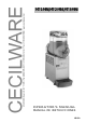
MT-1-MINI,MT-2-MINI,MT-3-MINI OPERATOR’S MANUAL MANUAL DE INSTRUCCIONES NS15A
MT MINI UL 2
10 29 This dispenser is manufactured under one or more of the following U.S.patents and/or other pending patents: Este aparato está cubierto por una o varias de las siguientes patentes y/o otras solicitudes de patente ya registradas: U.S.A. 4,900,158 U.S.A. 4,696,417 U.S.A. 5,713,214 U.S.A.
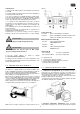
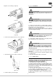
MT MINI UL 3 Install the unit on a counter top that will support the combined weight of dispenser and product bearing in mind what is stated in the preceding point 1 IMPORTANT warning. 4 A minimum of 15 cm (6”) of free air space all around the unit should be allowed to guarantee adequate ventilation. 5 Ensure that the legs are screwed tightly into the base of the machine. Replace the standard legs originally installed with the 100 mm (4”) legs whenever they are provided with the unit.
PROCEDURES. follows: 2 Fill the bowls with product to the maximum level mark. Do not overfill. The exact quantity of product (expressed as liters and gallons) is shown by marks on the bowl. 3 In case of products to be diluted with water, potable water, pour water into bowl first, then add correct quantity of product. In case of natural squashes, it is advisable to strain them, in order to prevent pulps from obstructing the faucet outlet.
MT MINI UL 2 Prior to the disassembly and cleaning, the machine must be emptied of product. To do this proceed as follows: - set the power switch to I position - set mixer/refrigeration switch(es) to I position (Soft Drink mode) - place a pail under each faucet and drain all product from bowls - set all control switches to the 0 position each switch box as follows: - towards right (clockwise) to decrease temperature. - towards left (counterclockwise) to increase temperature.
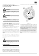
5. 3. 2 CLEANING magnetic rotor assembly (see figure 8). IMPORTANT Do not attempt to wash any machine components in a dishwasher. ATTENTION figure 7 Before any disassembly and/or cleaning procedure make sure that the dispenser is disconnected from its power source. 1 Prepare at least two gallons of a mild cleaning solution of warm (45-60 °C 120-140 °F) potable water and dishwashing detergent. Do not use abrasive detergent.
MT MINI UL 5. 3. 4 ASSEMBLY end of the magnetic outside rotor (see figure 14). 1 Slide the drip tray into place. 2 Lubrificare il pistone rubinetto e il rotore magnetico esterno (see points A, B and C of figure 11) only with the grease supplied by the manufacturer or other food grade approved lubricant. figure 14 7 Push the bowl towards the rear wall of the unit until it fits snugly around the gasket and its front fastening hooks are properly engaged (see figure 15).
automatically freezes down again to Granita setting viscosity. or damaged parts. Replace parts as needed. 2 Monthly on MT 2 MINI and MT 3 MINI models: remove the dust from the condenser filter. ATTENTION Before any disassembly and/or cleaning procedure make sure that the dispenser is disconnected from its power source by unplugging it or switching off the 2-pole wall breaker. ATTENTION Condenser fins are very sharp. Use extreme caution when cleaning. 6.
2 Controlar que el distribuidor no haya sufrido daños durante el transporte. De haberlos sufrido, reclamar inmediatamente al transportista. 3 Colocar el distribuidor en un mostrador en grado de sostener su peso incluso con la carga completa, teniendo en cuenta cuanto indicado en IMPORTANTE, del punto 1. 4 Dejar un espacio libre de por lo menos 6” alrededor del aparato para no impedir el flujo de aire de refrigeración. 5 Controlar la estabilidad del aparato, regulando la altura de los pies.
que alcance el nivel máximo indicado (no superar dicho nivel). La cantidad de producto presente en el contenedor (en litros o en galones) está indicada con señales específicas situadas en el contenedor mismo. apropiada (ver figura 1). 3 Si se quiere distribuir productos concentrados a diluirse con agua, verter en los contenedores el agua agregando a continuación la cantidad necesaria de producto concentrado, según las instrucciones del fabricante.
MT MINI UL particular, cerca de las rejillas de los paneles. Cerciorarse además, que el flujo de aire no esté obstaculizado por paredes cercanas, cajas u otras cosas. Dejar por lo menos 15 cm de espacio libre alrededor del distribuidor.En todo caso cuando el producto dentro de los contenedores está helado y la lamparilla del limitador de presión de seguridad está apagada es seguro que todo funciona regularmente y que el calor emitido no es dañoso.
4 Quitar de su alojamiento la junta del contenedor (ver figura 9). 6). figura 9 5 Desarmar el grifo respetando la secuencia indicada (ver figura 10). figura 5 figura 10 6 Desenfilar el cajón recoge-gotas y vaciarlo. figura 6 5. 3. 2 3 Desenfilar del evaporador el rascador exterior (ver figura 7) y después el Rotor magnetico externo completo (ver figura 8). LAVADO IMPORTANTE No lavar ningún componente de la maquina en lavavajillas.
MT MINI UL 2 Emplear un cepillo apropiado y lavar minuciosamente con la solución detergente todas las partes en contacto con la bebida. pared posterior (ver figura 12). ATTENCION Durante el lavado del distribuidor no usar mucha cantidad de agua cerca de los componentes eléctricos; en caso contrario es posible que se verifiquen shock eléctricos o bien se dañe el distribuidor. 3 No sumergir en la solución de lavado las tapas con luz sino que lavarlas en modo separado.
8 Enjuagar con bebida fresca para eliminar todo residuo posible de solución para higienizar del fondo de los contenedores. Secar la parte interior de los contenedores con una servilleta de papel desechable. 3 No quitar jamás el material aislante contra la condensación puesto alrededor del tubo de salida del evaporador (el tubo de cobre colocado a la derecha del motoreductor). Si dicho material estuviera dañado o perdido, reponer con recambios originales del fabricante. 5.
MT MINI UL SPARE PARTS LIST DESCRIPCION PIEZAS DE REPUESTO 16
2416_29 V 0.
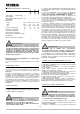
MT MINI UL 56 57 58 59 60 61 62 63 64 65 66 00153 00088 00452 00087 00573 00569 00707 00575 PPP 00157 00526 Rear bushing Spring Shaped nut Density adjustment screw Rear cover Rear cover fixing screw Rear cover picture Rear cover picture screen Back panel Timer cover Right side panel Buje posterior Muelle Tuerca-guida del muelle Tornillo regulador densidad Tapa posterior Tornillo de fijación de la tapa Fotografia para tapa posterior Armazón para fotografia tapa posterior Panel posterior Tapa para timer Pa
GEAR MOTOR MOTORREDUCTOR 1 00097 Bracket with bush 2 00156 Stator Soporte con buje Estator 3 00296 Stator protection gasket Junta de la cobertura estador 4 00168 Washer Arandella 5 00253 Rotor spacer Distancial del rotor 6 00190 Gear box with bushing Caja reductor con buje 7 00256 Seal retainer Junta de retencion 8 00254 Ball bearing ∅ 28 mm rubber cap Tapa de goma para cojinete 9 00255 Central shaft OR OR para eje central 10 00247 Ball bearing ∅ 28 mm Cojinete de bola
CECILWARE CORPORATION 43-05 20th Avenue Long Island City, N.Y. 11105 Tel. (800) 935 2211 Fax (718) 932 7860 Customer.Service@cecilware.com www.cecilware.com 2416_49 R0.