
Operating instructions

61
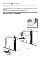
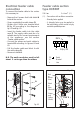
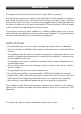
Electrical feeder cable
connection
To connect the feeder cable to the cooker
it is necessary to:
– Remove the 6 screws that hold shield A
behind the cooker.
– Open completely the cable clamp D.
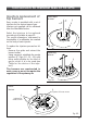
– Position the U bolts onto terminal block
B (fig. 63) according to the diagram in
fig. 64 and fig. 65.
– Insert the feeder cable into the cable
save P. The supply cable must be of a
suitable size for the current requirements
of the appliance; see the section
“Feeder cable section”.
– Connect the phase and earth cables to
terminal B according to figures 64 and
65.
– Pull the feeder cable and block it with
the cable clamp D.
– Re-mount shield A.
N.B. The earth conductor must be left
about 3 cm longer than the others.
Fig. 63
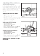
PE
12345
N (L2)L1
230 V
Fig. 64
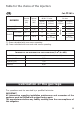
Feeder cable section
type H05RRF
230V 3 x 4 mm
2
(**)
(**) –
Connection with wall box connection.
– Diversity factor applied
– A diversity factor may be applied to
the total loading of the cooker only by
a suitable qualified person.
23451
230 V ~
N
(L
2)
PE
L1
Red
or
Brown
(Live)
Black
or
Blue
(Neutral)
Green
and
Yellow
(Earth)
Fig. 65
PE Earth
N Neutral
L Live
P
D
A
B