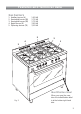
Dual fuel cookers RC 9000 ..
Dear Customer Thank you for choosing one of our appliances, carefully designed and built by our specialist staff and thoroughly tested to satisfy your cooking requirements. We suggest that you read this Instruction Booklet so that you will understand fully how to operate your appliance. Please keep the booklet handy. You may wish to refer to it at a later date. CDA IMPORTANT INFORMATION FOR CORRECT DISPOSAL OF THE PRODUCT IN ACCORDANCE WITH EC DIRECTIVE 2002/96/EC.
Contents Model RC 9000 .. Page Number Introduction . . . . . . . . . . . . . . . . . . . . . . . . . . . . . . . . . . . . . . . . . . . . . . 4 Features and technical data . . . . . . . . . . . . . . . . . . . . . . . . . . . . . . . . . . . 5 Control panel . . . . . . . . . . . . . . . . . . . . . . . . . . . . . . . . . . . . . . . . . . . . . 6 Electronic programmer . . . . . . . . . . . . . . . . . . . . . . . . . . . . . . . . . . . . . . 7 How to use the hob burners . . . . . . . . . . . . . . . . .
Introduction Congratulations on your purchase of this CDA cooker which has been carefully designed and produced to give you many years of satisfactory use. Before using this appliance it is essential that the following instructions are carefully read and fully understood. We would emphasise that the installation section must be fully complied with for your safety to ensure that you obtain the maximum benefits from your appliance.
Features and technical data Gas burners 1. 2. 3. 4. 5. Auxiliary burner (A) Semi-rapid burner (SR) Semi-rapid burner (SR) Rapid burner (R) Triple-ring burner (TR) 1,00 kW 1,75 kW 1,75 kW 3,00 kW 3,50 kW 5 4 3 1 2 Identification label Fig. 2 When you open the oven door the indentification label is at the bottom right hand side.
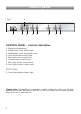
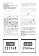
Control panel Fig. 3 9 A U T O 1 2 3 4 5 6 7 8 CONTROL PANEL - Controls description 1. 2. 3. 4. 5. 6. 7. 8. Electronic programmer Multifunction oven switch knob Multifunction oven thermostat knob Front left burner control knob Rear left burner control knob Central burner control knob Rear right burner control knob Front right burner control knob Pilot lamp: 9.
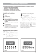
Electronic programmer The electronic programmer is a device that groups together the following functions: – 24 hour clock with illuminated display – Timer (up to 23 hours and 59 minutes) – Programme for automatic oven cooking – Programme for semi-automatic oven cooking.
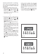
Electronic clock (fig. 5) Electronic timer The programmer is equipped with an electronic clock with lighted numbers which indicate hours and minutes. Upon immediate connection of the oven or after a blackout, three zeroes will flash on the programmer panel. To set the hour it is necessary to push the button and then the or button until you have set the exact hour (fig. 5). Alternatively, simultaneously push the two buttons and at the same time push the or button.
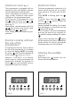
Automatic oven cooking To cook food automatically in the oven, it is necessary to: 1.Set the length of the cooking time 2.Set the end of the cooking time 3.Set the temperature and the oven cooking programme. These operations are done in the following way: 1.Set the length of the cooking time by pushing the button and the advance, or to go back button to if you have passed the desired time (fig. 8). The AUTO and the symbol will be on. 2.
Semi-automatic cooking This is used to automatically switch off the oven after the desired cooking time has elapsed. There are two ways to set your oven: 1. Set the length of the cooking time by pushing the button and the button to advance, or to go backwards if you have passed the desired time (Fig. 10). At the end of cooking, the oven and the symbol will turn off, the AUTO will flash and a buzzer will sound; that can be stopped by pushing any of the buttons.
How to use the hob burners Hob burners Each hob burner is controlled by a separate gas tap operated by a control knob (fig. 12) which has 3 positions marked on the control panel, these are: – Symbol ● : tap closed (burner off) – Symbol : High (maximum) – Symbol : Low (minimum) Push in and turn the knob anti-clockwise to the selected position. Fig. 12 To turn the burner off, fully rotate the knob clockwise to the off position: ●.
Choice of burner The burner must be choosen according to the diameter of the pans and energy required. Burners Pan diameter Auxiliary Semi-rapid Rapid Triple-ring Wok 12 ÷ 14 cm 16 ÷ 24 cm 24 ÷ 26 cm 26 ÷ 28 cm max 36 cm Fig. 13 do not use pans with concave or convex bases Saucepans with handles which are excessively heavy, in relationship to the weight of the pan, are safer as they are less likely to tip. Pans which are positioned centrally on burners are more stable than those which are offset.
How to use the Multifunction oven General features As its name indicates, this is an oven that presents particular features from an operational point of view. In fact, it is possible to insert 7 different programmes to satisfy every cooking need.
Fig. 15 Fig. 16 Thermostat knob (Fig. 16) This only sets the cooking temperature and does not switch the oven on. Rotate clockwise until the required temperature is reached (from 50 to 250°C). The light between the thermostat and the function selector will illuminate when the oven is switched on and turns off when the oven reaches the correct temperature. The light will cycle on and off during cooking in line with the oven temperature. Function selector knob (Fig.
Grilling The infrared grill element comes on. The heat is dispersed by radiation. Use with the oven door closed and the thermostat knob to position 225°C for max 15 minutes, then to position 175°C. For cooking hints, see the chapter “USE OF THE GRILL”. Recommended for: Intense grilling, browning, cooking au gratin and toasting etc. It is recommended that you do not grill for longer than 30 minutes at any one time. Caution: the oven door becomes very hot during operation. Keep children well out of reach.
Ventilated grill cooking The infrared grill element and the fan come on. The heat is dispersed mainly by radiation and the fan then distributes it all over the oven. Use with the door closed. The temperature can be regulated via the thermostat knob to between 50° and 175° max. The oven must be preheated for approximately 5 minutes. For cooking hints, see the chapter “GRILLING AND AU GRATIN. Recommended for: Grilling where quick browning on the outside is required to keep the juices in.
Cooking advice Sterilization Sterilization of foods to be conserved, in full and hermetically sealed jars, is done in the following way: a. b. c. d. Set the switch to position . Set the thermostat knob to position 185 °C and preheat the oven. Fill the dripping pan with hot water. Set the jars onto the dripping pan making sure they do not touch each other and the door and set the thermostat knob to position 135 °C.
Grilling and “au gratin” Grilling may be done without the roasting jack on position of the switch, because the hot air completely envelops the food that is to be cooked. Set the thermostat to position 175 °C and after having preheated the oven, simply place the food on the rack. Close the door and let the oven operate with the thermostat on position 175 °C, until grilling is done. Adding a few dabs of butter before the end of the cooking time gives the golden “au gratin” effect.
Important notes Installation, and any demonstration, information or adjustments are not included in the warranty. The cooker must be installed by a qualified person in accordance with the relevant Standards. In the UK C.O.R.G.I registered installers are authorised to undertake the installation and service work in compliance with the applicable regulations.
Do’s and do not’s Do’s and do not’s • Do always grill with the oven door closed. • Do read the user instructions carefully before using the cooker for first time. • Do allow the oven to heat for one and a half hours, before using for the first time, in order to expel any smell from the new oven insulation, without the introduction of food. • Do clean your oven regularly. • Do remove spills as soon as they occur. • Do always use oven gloves when removing food shelves and trays from the oven.
Care and maintenance Important: As a safety measure, before you start cleaning the cooker be sure to disconnect it from the mains supply. Do not use a steam cleaner because the moisture can get into the appliance thus make it unsafe. The use of suitable protective clothing/gloves is recommended when handling or cleaning of this appliance. WARNING When correctly installed, your product meets all safety requirements laid down for this type of product category.
Enamelled parts All the enamelled parts must be cleaned with a sponge and soapy water only or other non-abrasive products. Dry preferably with a microfibre or soft cloth. Stainless steel, aluminium, painted parts and silkscreen printed surfaces Clean using an appropriate product. Always dry thoroughly. Stainless steel surfaces: can be cleaned with an appropriate stainless steel cleaner. IMPORTANT: these parts must be cleaned very carefully to avoid scratching and abrasion.
Burners They can be removed and washed only with soapy water. Detergents can be used but must not be abrasive or corrosive. Do not use abrasive sponges or pads. Do not put in dishwasher. After each cleaning, make sure that the burner-caps, as well as the burners, have been well wiped off and CORRECTLY POSITIONED. It is essential to check that the burner flame distributor F and the cap C has been correctly positioned (see fig. 17) failure to do so can cause serious problems.
Removal of the inner glass door panel – The inner glass door panel can easily be removed for cleaning by unscrewing the four screws (fig. 20). – When re-assembly ensure that the inner glass is correctly positioned and do not over tighten the screws. Do not use harsh abrasive cleaners or sharp metal scrapers to clean the oven door glass since they can scratch the surface, which may result in shattering of the glass. Fig.
Inside of oven The oven should always be cleaned after use when it has cooled down. The cavity should be cleaned using a mild detergent solution and warm water. Suitable proprietary chemical cleaners may be used after first consulting with the manufacturers recommendations and testing a small sample of the oven cavity. Abrasive cleaning agents or scouring pads/cloths should not be used on the cavity surface.
Oven tray The oven tray must be correctly placed on the wire support (fig. 24) then inserted into the side runners (fig. 25). Oven floor The oven floor “F” (fig. 25) can be easily removed to facilitate cleaning. Remember to replace the floor correctly afterwards. Be careful not to confuse the tray “L” with the oven floor “F”. Fig. 24 L F Fig.
Removing the oven door Fig. 26a Please operate as follows: ● ● ● ● Open the door completely. The swivel retainers of the rh and lh hinges (fig. 26a) are hooked onto the metal bar above them (fig. 26b). Lift the oven door slightly. The noch on the bottom of the hinge will disengage (fig. 26c). Now pull the oven door forwards off the appliance. Release both hinge sections from the slots (fig. 26d). Fig.
FOR THE INSTALLER The appliance may be installed in a kitchen, Kitchen/diner or a bed sitting room, but not in a room or space containing a bath or a shower. The appliance must not be installed in a bed-sitting room of less than 20 m3. The appliance is designed and approved for domestic use only and should not be installed in a commercial, semi commercial or communal environment.
Location This cooker has class “2/1” overheating protection so that it can be installed next to a cabinet. If the cooker is installed adjacent to furniture which is higher than the gas hob cooktop, a gap of at least 200 mm must be left between the side of the cooker and the furniture. The furniture walls adjacent to the cooker must be made of material resistant to heat. The veneered synthetic material and the glue used must be resistant to a temperature of 90°C in order to avoid ungluing or deformations.
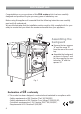
Fitting the adjustable feet The adjustable feet must be fitted to the base of the cooker before use. Rest the rear of the cooker an a piece of the polystyrene packaging exposing the base for the fitting of the feet. Fig. 28 Fit the 4 legs by screwing them tight into the support base as shown in picture 29. WARNING When raising cooker to upright position always ensure two people carry out this manoeuvre to prevent damage to the adjustable feet (fig. 30). Fig. 29 Fig.
WARNING Be carefull: do not lift the cooker by the door handle when raising to the upright position (fig. 31). WARNING When moving cooker to its final position DO NOT DRAG (fig. 32). Lift feet clear of floor (fig. 30). Fig. 31 Fig. 32 Levelling the cooker The cooker may be levelled by screwing the lower ends of the feet IN or OUT (fig. 33). Fig.
Stability bracket We recommend a stability bracket is fitted to the cooker. The type shown in fig. 34 can be purchased from most plumbers merchants and do it yourself (D.I.Y.) shops. Existing slot in rear of cooker Brackets Fig.
Provison for ventilation ✓ The appliance should be installed into a room or space with an air supply in accor- dance with BS 5440-2: 2000. ✓ For rooms with a volume of less than 5 m3 - permanent ventilation of 100 cm2 free area will be required. ✓ For rooms with a volume of between 5 m3 and 10 m3 a permanent ventilation of 50 cm2 free area will be required unless the room has a door which opens directly to the outside air in which case no permanent ventilation is required.
Gas installation IMPORTANT NOTE This appliance is supplied for use on NATURAL GAS or LPG (check the gas regulation label attached on the appliance). ✓ Appliances supplied for use on NATURAL GAS: they are adjusted for this gas only and cannot be used on any other gas (LPG) without modification. The appliances are manufactured for conversion to LPG. ✓ Appliances supplied for use on LPG: they are adjusted for this gas only and cannot be used on any other gas (NATURAL GAS) without modification.
Gas connection The installation of the gas appliance to Natural Gas or LP Gas must be carried out by a C.O.R.G.I. registered installer. Installers shall take due account of the provisions of the relevant British Standards Code of Practice, the Gas Safety Regulations and the Building Standards (Scotland)(Consolidation) Regulations issued by the Scottish Development Department. Installation to Natural Gas Installation to Natural Gas must conform to the Code of Practice, etc.
Gas connection GB Cat: II 2H3+ The gas supply must use the nearest gas inlet pipe which is located at the left or the right hand side at the rear of the appliance (figs. 35, 37). The hose should also be connected in such away that it does not touch the floor. To screw the connecting tube operate with two spanners (fig. 36). The unused end inlet pipe must be closed with the plug interposing the gasket.
IMPORTANT PRESCRIPTIONS FOR GAS CONNECTION 700 mm Rear wall 200 mm Suggested area for gas mains connection Fig.
Conversion to Natural Gas or to LPG Injectors replacement of top burners Every cooker is provided with a set of injectors for the various types of gas. Injectors not supplied can be obtained from the After-Sales Service. Select the injectors to be replaced according to the table at page 40. The nozzle diameters, expressed in hundredths of a millimetre, are marked on the body of each injector. To replace the injectors proceed as follows: – Remove the grids and extract the burner bodies.
Adjusting of the minimum of the top burners Considering that in the minimum position the flame must have a length of about 4 mm and must remain lit even with a quick turn from the maximum position to that of minimum. The flame adjustment is done in the following way: – Turn on the burner – Tum the tap to the MINIMUM position – Take off the knob – With a small flat screwdriver turn the screw inside the tap rod to the correct regulation (fig. 40). Normally for LPG, tighten up the regulation screw. Fig.
Table for the choice of the injectors GB Cat: G 30 - 28-30 mbar G 31 - 37 mbar Reduced Power [kW] [kW] By-pass [1/100 mm] [1/100 mm] Auxiliary (A) 1,00 0,30 27 50 Semi-rapid (SR) 1,75 0,45 32 65 Rapid (R) 3,00 0,75 42 85 Triple-ring (TR) 3,50 1,50 65 95 INCREASE BURNERS Ø injector OF AIR NECESSARY FOR GAS COMBUSTION Ø injector By-pass [1/100 mm] [1/100 mm] 72 (X) adjustable Nominal Power BURNERS II 2H3+ G 20 20 mbar 97 (Z) 115 (Y) 135 (T) (2 m3/h x kW) Air necessary f
Electrical installation The appliance must be connected to the electrical network verifying above all that the voltage corresponds to the value indicated on the specifications plate and that the cables section of the electrical plant can bear the load which is also indicated on the plate. The cooker can be connected directly to the mains placing an omnipolar switch with minimum opening between the contacts of 3 mm between the appliance and the mains.
Appliance servicing CDA provide a quality and effective after-sales service to cover all your servicing needs. Please attach your receipt to this page for safekeeping. Please help us to help you by having the following information available when booking a service-call: 1. Model type, make and model – see the product data plate. 2. Evidence of installation / purchase date 3. Retailer where appliance was purchased 4. Clear and concise details of the fault 5.
Guarantee CDA appliances carry a five-year parts and a one-year labour guarantee. CDA will repair or replace any defect or part attributable to faulty material or workmanship. Within the first year this will be free of both labour and parts charges. After the first year and within five years, the parts will be supplied free of charge provided that the repair is carried out by an agent authorised by CDA and the labour will be charged at the commercial rate applicable at the time of repair.
Descriptions and illustrations in this booklet are given as simply indicative. The manufacturer reserves the right, considering the characteristics of the models described here, at any time and without notice, to make eventual necessary modifications for their construction or for commercial needs. Cod. 1103119 ß5 RC 9000 ..