
Instruction Manual


208
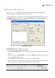
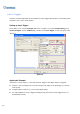
[Input X] Click the Arrow buttons to select an Input to set up. One GV-IO module provides up to 8
inputs.
Figure 6-2
Name evice in the Name field. (Click the Arrow button to set up
elect signal type for your input device. You may use the Finger button to apply
ch Trigger later in this chapter.
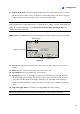
onitor Input]
heck this option to use the input (sensors or detectors) to trigger recordings on
o activate computer alarm when the input is triggered. You may
nd out an assigned alert (E-Mail/Hotline/SMS)
ears when E-Mail is the assigned alert. Click to select the camera(s)
ts
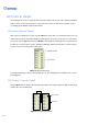
input is invoked, the system will automatically send a signal to an output
Arrow button: Click to set the delay time to activate the assigned output module.
: Specifies a name for each input d
next input).
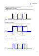
Signal Type: S
your selection to all input devices.
For details on Latch Trigger, see Lat
[M
Rec Video: C
multiple cameras. Click the Arrow button to select which camera to record upon input trigger, and
specify the recording duration.
Invoke Alarm: Check this option t
select the alarm type in the drop-down menu.
Invoke to Send Alerts: Check this option to se
when the input is triggered.
1st Right Arrow button: App
to take a snapshot on input trigger. The snapshot will be sent out by E-Mail.
2nd Right Arrow button: Click to set the delay time to activate assigned aler
(E-Mail/Hotline/SMS).
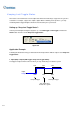
Output Module: If the
pin.
Right