Chipley Custom Machine .45 or 86 Degree Grip Manual V 1.0 CCM / DPM 19641 N. Hirsch St Anderson, Ca 96007 Phone- 530-378-3420 Sales- 1-877-412-6850 Fax- 530-378-3420 www.chipleymachine.
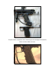
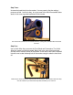
This photo shows a comparison of the .45 frame (top) and an 86 degree frame (bottom). Below is a Series 5 Basic .45 frame.
I. Table of Contents: I. Liability Page 4 II. Safety and Handling Page 5 III. Parts List Page 6 IV. Disassembly in Preparation for Installation Page 7 V. Assembly Page 11 VI.
II. Liability: Chipley Custom Machine and Datum Precision Machining (CCM / DPM) does not accept any liability for the handling of these markers, tools, air tanks, or any other item mentioned in this manual. You, the user accept this sole liability when purchasing and using any paintball marker or paintball accessories. We, CCM / DPM, disclaim any implied warranties or any responsibility for any errors that may appear in this manual.
III. Safety and Handling: A Paintball Marker is not a toy. Any of the tools in this manual are not toys. Tools and paintball markers should be used only by adults or with adult supervision. Respect other peoples’ property and when using any paintball marker, obey all local, state and federal laws. When entering a paintball field, become aware of their rules and regulations. It is very important to have the proper paintball protection before going to the paintball field for play.
IV. CCM Grip Frame Parts List: Part Material 86 Degree or .45 Hinge Frame 6061 Aluminum Trigger Delrin Trigger Bearing Trigger Bearing Pin Steel Sear Sear Pin Steel Sear Pin Lock Screw Stainless Steel (not present on the S5 or S5B) Sear Spring (Same as Valve Spring) Lee Springs Grips (on 86 degree grip) Delrin Grips (optional on 86 degree grip) Grips on .
V. Disassembly of a Stock Autococker for preparation of a CCM Deluxe Kit and Grip Frame: Schematic of a 2004 WGP Prostock® Autococker®. Your ‘cocker might differ – but the parts are essentially the same. Step One: Remove Bolt Pin and Slide Bolt from the Body of the marker and the Back Block. Step Two: Remove Cocking Rod from the marker. The back of the marker as it looks after Step One and Two.
Step Three: Unscrew the back block from the marker. You may need to flex the cocking / pump arm a little - but this is okay. In my the case of the 2004 Prostock® it takes about 10 full turns to get the back block off the marker. Your marker will look like this once the Bolt, Bolt Pin, Cocking Rod, and Back Block have been removed. Step Four: Use a 3/16th Allen Key to remove the Front Block and Pneumatics.
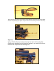
This is what your front block and pneumatics will look like when removed from the marker. Note that the 4-way actuating rod, coupler, and spool did not come with the pneumatics. This is okay. Step Five: Using a .50 Allen Key remove the grub screw that retains the Actuating Rod Coupler to the Actuating Rod. Unscrew the Coupler. In my case it took 9.5 turns to remove the coupler from the Actuating Rod.
Step Six: Using a 1/8th Allen Key remove the two screws that hold the grip frame on the marker. Slide the Actuating Rod through the Vertical Regulator Adapter and remove it. Screw the Actuating Rod back on the coupler of the pneumatics and set them aside.
VI. Assembly of the CCM Grip Frame on a Stock Autococker®: Step One: Insert the Guide Rod and Guide Ring (being sure the o-ring is slightly lubricated) into the threaded portion where you removed the Banjo Bolt. Step Two: Optional: Slide a return spring (not supplied but one can be purchased through CCM) over the top (larger) guide rod and then slide the pump over the guide rod. If you don’t want a return spring skip this step.
Step Four: Screw the Back Block on to the Pump Rod until it is tight on the Pump Rod. It might not tighten down on the Pump Rod and this is not essential. Just get it close to the end of the threads. Step Five: Reinsert the Bolt, Bolt Pin, and Cocking Rod into the rear of the marker.
Step Seven: Slide the Auto Trigger assembly into the hole in the side of the frame and attach it to the pump rod (5/64ths). Step Eight: Time the Auto Trigger by ensuring that the marker fires while holding down the trigger where the back block is 1/8th of an inch away from the body. To do this adjust the lug of the bolt (1/8th - long handled Allen Key) until the back block is in the right position when the trigger is depressed. Above: Proper Spacing - as shown on a Series 5 Basic.
Below: Adjusting the lug on also shown on a Series 5 Basic. Step Nine: Adjust the undertravel screw so that the Auto Trigger cam does not block the trigger pull. The under travel screw sets where the pull of the trigger begins and also holds the Cam in place. Above: The access hole to the Undertravel screw is shown by the bottom Allen key. Pump the marker until you hear the sear ‘click’. Allow the pump to sit at this point and adjust the undertravel screw until it touches the trigger.
This should set the undertravel screw to the proper position. Essentially you want to set the trigger as short as you can without causing binding on the pump stroke. You have set the undertravel too short if you feel binding in the rear portions of the pump stroke. That should be it.
VII. Disassembly of a CCM Grip Frame for Maintenance: 1. Remove the screw that attaches the auto trigger arm and cam to the frame. 2. Remove the grip screws (4 - 5/64th) and the grip panels and the Frame Screws (2 1/8th Allen Screws for the Series 5 Basic and 2 - 3/32nd for the Series 6) that attach the frame to the marker chassis. The screws on the Series 6 are submerged and thus can be simply loosened a turn or two and the frame slid to the rear of the marker and removed.
5. Step Four (Series 6 Frame - Not Pictured): Carefully (the sear is under slight spring tension) remove the sear retention pin. There is a small grub screw to remove and then a small pin can be used to push out the sear retention pin. 6. The Sear, Sear Pin, and Spring will come out. 7. Inspect the Sear to see if it has wear where the lug catches. (Notice the slight wear on this sear.) Wear can cause the marker to ‘skip’ (not recock from time to time) or be VERY hard to time the auto trigger.
8. Remove the Trigger Shoulder Bolt and slide the trigger from the frame (shown with the top Allen key). Also remove the Trigger Undertravel Screw (shown with the bottom Allen key) - it must be removed from the top of the frame. Use Blue Loctite® on these screws upon reassembly. Be sure not to over tighten the Trigger Shoulder Bolt. Over tightening can cause drag on the trigger. 9. Your trigger frame is now completely disassembled. Clean thoroughly and reassemble.