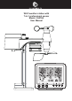
WI-FI weather station with 7-In-1 professional sensor Model: C6078A User Manual
TABLE OF CONTENTS PRECAUTIONS . . . . . . . . . . . . . . . . . . . . . . . . . . . . . . . . . . . . . . . . . . . . . . . 1 INTRODUCTION. . . . . . . . . . . . . . . . . . . . . . . . . . . . . . . . . . . . . . . . . . . . . . 1 OVERVIEW. . . . . . . . . . . . . . . . . . . . . . . . . . . . . . . . . . . . . . . . . . . . . . . . . CONSOLE. . . . . . . . .
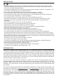
PRECAUTIONS -- Keep and reading the “User manual” is highly recommended. The manufacturer and supplier cannot accept any responsibility for any incorrect readings, export data lost and any consequences that occur should an inaccurate reading take place. -- This product is designed for use in the home only as indication of weather conditions. This product is not to be used for medical purposes or for public information -- Do not subject the unit to excessive force, shock, dust, temperature or humidity.
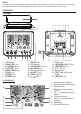
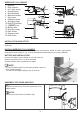
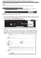
NOTE: This instruction manual contains useful information on the proper use and care of this product. Please read this manual through to fully understand and enjoy its features, and keep it handy for future use. OVERVIEW CONSOLE 1 11 12 13 14 15 16 2 3 1. 2. 3. 4. 5. 6. 7. 8. 4 5 Table stand [ SNOOZE ] key [ CHANNEL ] key [ HISTORY ] key [ MAX / MIN ] key [ SUN ] key [ WIND ] key [ BARO ] key 6 7 8 9 10 17 18 9. [ RAIN ] key 10. LCD display 11. [ CLOCK SET ] key 12.
WIRELESS 7-IN-1 SENSOR 1 1. Antenna 2. Rain collector 3. UVI / light sensor 2 4. Mounting pole 5. Mounting base 3 6. Balance indicator 7. Wind vane 8. Radiation shield 9. Mounting clamp 10. Red LED indicator 11. [ RESET ] key 12. Battery door 4 13. Mounting clamp 14. Rain sensor 15. Tipping bucket 16. Drain holes 10 11 6 12 7 8 13 9 14 15 16 5 INSTALLATION AND SETUP Your console can pair up with one wireless 7-in-1 wireless sensor and up to 7 wireless indoor sensors.
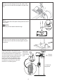
Step 2 Place the nut in the hexagon hole on the sensor, then insert the screw in other side and tighten it by the screw driver. Step 3 Insert the other side of the pole to the square hole of the plastic stand. NOTE: Ensure the pole and stand's indicator align. Step 4 Place the nut in the hexagon hole of the stand, then insert the screw in other side and then tighten it by the screw driver.
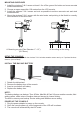
MOUNTING GUIDELINES 1. Install the wireless 7-IN-1 sensor at least 1.5m off the ground for better and more accurate wind measurements. 2. Choose an open area within 150 meters from the LCD console. 3. Install the wireless 7-IN-1 sensor as level as possible to achieve accurate rain and wind measurements. 4. Mount the wireless 7-IN-1 sensor with the wind meter end pointing to the North to correctly orient direction of the wind vane. A. Mounting on pole (Pole Diameter 1"~1.3") (25~33mm) B.
NOTE: If no display appears on the LCD after you plug the adaptor, press [ RESET ] key by using a pointed object. SET LCD DISPLAY VIEWING ANGLE Press [ ] or [ ] key in normal mode to adjust LCD viewing angle to fit table stand or wall mount situation. BUILT-IN MEMORY The console has built-in FLASH memory that holds the vital settings.
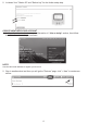
CREATE WEATHER SERVER ACCOUNT & SETUP WI-FI CONNECTION The console can upload weather data to WUnderground and / or Weathercloud through WI-FI router, you can follow the step below to setup your device . NOTE: The Weather Underground and Weathercloud website are subjected to change without notice . CREATE WEATHER UNDERGROUND ACCOUNT 1 . In https://www.wunderground.com click the "Join" on the top right corner to open the registration page . Follow the instructions to create your account .
5 . Jot down Your "Station ID" and "Station key" for the further setup step . CREATE WEATHERCLOUD ACCOUNT 1 . In https://weathercloud.net enter your information in "Join us today" section, then follow the instructions to create your account . NOTE: Use the valid email address to register your account . 2 . Sign in weathercloud and then you will go the "Devices" page, click "+ New" to create new device .
3 . Enter all the information in Create new device page, for the Model* selection box select the "W100 Series" under "CCL" section . For the Link type* selection box select the "SETTINGS", Once you have completed, click Create . 4 . Jot down your ID and key for the further setup step .
SETUP WI-FI CONNECTION 1 . When you power up the console for the first time, the console LCD will show flashing "AP" and " " icon to signify that it has entered AP (Access Point) mode, and is ready for WI-FI settings . User can also press and hold the [ SENSOR / WI-FI ] key for 6 seconds to enter AP mode manually . 2 . Use the smart phone, tablet, or computer to connect the console through WI-FI . WI-FI to select the 3 .
SETUP THE WEATHER SERVER CONNECTION Enter the following information into the below web interface "SETUP" page to connect the console to weather server, If you do not want to use Wunderground.com or Weathercloud.net, please empty the station ID & key to ignore the data upload.
TIME SERVER CONNECTION STATUS After the console has connected to the Internet, it will attempt to connect to the Internet time server to obtain the UTC time . Once the connection succeeds and the console time has been updated, the “ ” icon will appear on the LCD . The time will automatically synchronize Internet time server at 12:00AM and 12:00PM per day . Also you can press the [ REFRESH ] key to get the Internet time manually within 1 minute .
NOTE: - Calibration of most parameter is not required, with the exception of Relative Pressure, which must be calibrated to sea-level to account for altitude effects. VIEW YOUR WEATHER DATA IN WUNDERGROUND To view your weather station live data in a web browser (PC or mobile version), please visit http://www. wunderground.com, and then enter your “Station ID” in the searching box . Your weather data will show up on the next page .
FIRMWARE UPDATE STEP 1. Download the latest version firmware to your PC. 2. Set the Console into AP (access point) mode then connect the PC to the console (ref to "SETUP WI-FI CONNECTION" section in previous page). Browse 3. Click the in firmware update section and browse the location of the file you Browse download in step 1. To update the WI-FI firmware, click the in WI-FI firmware section. Upload to start transfer the firmware file to console. 4. Click the corresponding 5.
3. Press [ ALARM ] key again to step the setting value to Minute with the Minute digit flashing. 4. Press [ ] or [ ] key to adjust the value of the flashing digit. 5. Press [ ALARM ] key to save and exit the setting. NOTE: -- In alarm mode, the “ ” icon will display on the LCD. -- The alarm function will turn on automatically once you set the alarm time. ACTIVATING ALARM AND TEMPERATURE PRE-ALARM FUNCTION 1. In normal mode, press [ ALARM ] key to show the alarm time for 5 seconds. 2.
TEMPERATURE / HUMIDITY FUNCTION -- The temperature and humidity reading are display on the out and in / CH section. -- Use the [ °C / °F ] slide switch to select the temperature display unit. -- If temperature / humidity is below the measurement range, the reading will show “Lo”. If temperature / humidity is above the measurement range, the reading will show “HI”.
TO SET THE WIND SPEED UNIT AND DIRECTION DISPLAY FORMAT 1. In normal mode, press and hold [ WIND ] key for 2 seconds to enter into wind speed unit mode and the unit will flash. Press [ ] or [ ] key to change the wind speed unit in this sequence: m/s km/h knots mph 2. Press [ WIND ] key again to enter wind direction setting mode. The wind direction reading will flash, and then press [ ] or [ ] key to select the display format between 360 degree or 16 direction. 3.
9 Strong gale 10 Storm 11 Violent storm 12 Hurricane force 75 ~ 88 km/h 47 ~ 54 mph 41 ~ 47 knots 20.8 ~ 24.4 m/s 89 ~ 102 km/h 55 ~ 63 mph 48 ~ 55 knots 24.5 ~ 28.4 m/s 103 ~ 117 km/h 64 ~ 73 mph 56 ~ 63 knots 28.5 ~ 32.6 m/s ≥ 118 km/h ≥ 74 mph ≥ 64 knots ≥ 32.7m/s Some branches break off trees, and some small trees blow over. Construction / temporary signs and barricades blow over. Trees are broken off or uprooted, structural damage likely. Widespread vegetation and structural damage likely.
WEATHER FORECAST The built-in barometer continually monitor atmosphere pressure. Based on the data collected, it can predict the weather conditions in the forthcoming 12~24 hours within a 30~50km (19~31 miles) radius. Sunny Partly cloudy Cloudy Rainy Rainy / Stormy Snowy NOTE: -- The accuracy of a general pressure-based weather forecast is about 70% to 75%. -- The weather forecast is reflecting the weather situation for next 12~24 hours, it may not necessarily reflect the current situation.
TO RESET THE TOTAL RAINFALL RECORD In normal mode, press and hold [ HISTORY ] key for 2 seconds to reset all the rainfall record. NOTE: To ensure to have correct data, please reset all the rainfall record when you reinstall your wireless 7-IN-1 sensor to other location. LIGHT INTENSITY, UV INDEX & SUNBURN TIME This section of display show the sunlight intensity, UV index and sunburn time. Press the [ SUN ] key to change the mode. LIGHT INTENSITY MODE: 1.
TO CLEAR THE MAX/MIN RECORDS Press and hold [ MAX / MIN ] key for 2 seconds to reset the current on display MAX or MIN records. NOTE: The LCD will also display the " "/" ", " " icon, data records time & date. PAST 24 HOURS HISTORY DATA The console automatically stores the weather data of the past 24 hours. 1. Press [ HISTORY ] key to check the beginning of the current hour's weather data, e.g. the current time is 7:25 am, March 8, the display will show the data of 7:00am, March 8. 2.
6. Press [ ALERT ] key to shift to next alert reading. High / Low Alert on Alert off Alert on Alert off 7. Press any key on the front side to save alert on /off status and back to normal mode, or it will automatically back to normal mode after 30 seconds without pressing any key. TO SILENCE THE ALERT ALARM Press [ SNOOZE ] key to silence the alert alarm or let the alarm automatically turn off after 2 minutes.
WIRELESS 7-IN-1 SENSOR MAINTENANCE REPLACE THE WIND CUP 1. Remove rubber cap and Unscrew 2. Remove the wind cup for replacement CLEANING THE RAIN COLLECTOR 1. Rotate the rain collector by turning it 30°anti-clockwise. 2. Gently remove the rain collector. 3. Clean and remove any debris or insects. 4. Install the collector when it is clean and fully dried. CLEANING THE UV SENSOR AND CALIBRATION • For precision UV measurement, gentle clean the UV sensor cover lens with damp micro-fiber cloth.
Temperature reading too high in the day time 1. Place the sensor in open area and at least 1.5m off the ground. 2. Make certain that the sensor array is not too close to heat generating sources or strictures, such as buildings, pavement, walls or air conditioning units. SPECIFICATIONS CONSOLE General Specification Dimensions (W x H x D) Weight Main power Backup battery Operating temperature range Operating Humidity range 118 x 192.
Indoor Temperature (Note: Data detect by console) Temperature unit Accuracy Resolution Memory modes °C and °F <0°C or >40°C ± 2°C (<32°F or >104°F ± 3.6°F) 0~40°C ±1°C (32~104°F ± 1.8°F) °C / °F (1 decimal place) Historical data of past 24 hours, daily Max / Min Indoor Humidity (Note: Data detect by console) Humidity unit Accuracy Resolution Memory modes % 1 ~ 20% RH ± 6.5% RH @ 25°C (77°F) 21 ~ 80% RH ± 3.5% RH @ 25°C (77°F) 81 ~ 99% RH ± 6.
LIGHT INTENSITY (Note: Data detect by 7-in-1 sensor) Light intensity unit Display range Resolution Memory modes Klux, Kfc and W/m² 0 ~ 200Klux Klux, Kfc and W/m² (2 decimal place) Historical Data of past 24 hours, Max Weather Index (Note: Data detect by 7-in-1 sensor) Weather index mode Feels like, Wind Chill, Heat Index and Dew point Feels like display range -65 ~ 50°C Dew point display range -20 ~ 80°C Heat index display range 26 ~ 50°C Wind chill display range -65 ~ 18°C (wind speed > 4.
27