
Manual

2
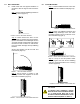
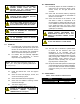
4.0 INSTALLATION - REFLECTOR BAFFLES
4.1 REFLECTOR BAFFLES (T2D units only).
Refer to Figure 1 when installing reector
bafes.
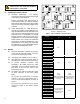
FIGURE 1 - REFLECTOR BAFFLES INSTALLATION
TABLE 1 - REFLECTOR BAFFLE PAIRS PER HEAT SINK
Heat Sink Extrusion
Length
# of Pairs
Size
in mm in mm
5.1 130 0 - -
11.8 300 1 8 203
18.5 470 2 8 203
25.2 640 1 24 610
NOTE: Bafes are only required for units with a T2D
temperature code rating.
4.2 Position heater front face down on a at
surface.
4.3 With the fold in the bafe positioned between
the keyhole n and the adjacent short n, slide
reector bafes onto the back of heat sink.
4.4 Ensure reector bafes are secure in place
and ush with the top of the heat sink. If
reector bafes move freely, open the fold
with a screw driver to improve the friction and
reinstall bafes.
CAUTION
THE HEATERS SURFACE IS HOT WHEN
THE HEATER IS ENERGIZED. KEEP ALL
COMBUSTIBLES AWAY FROM THE HEATER
AND MAINTAIN THE RECOMMENDED
INSTALLATION CLEARANCES AT ALL TIMES.
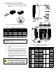
FIGURE 2 - DIMENSIONS & MOUNTING DETAILS
TABLE 2 - HEATER DIMENSIONS
Unit
B F G M N L
in (mm) in (mm) in (mm) in (mm) in (mm) in (mm)
XB1
7.250
(184)
10.250 (260) 9.625 (244)
- -
5.125 (130)
XB1 17.000 (432) 16.375 (416) 11.875 (300)
XB1 23.625 (600) 23.000 (584) 18.500 (471)
XB1 30.375 (772) 29.750 (756) 25.250 (640)
XB2
16.125
(410)
10.250 (260) 9.625 (244)
7.125
(181)
8.250
(210)
5.125 (130)
XB2 17.000 (432) 16.375 (416) 11.875 (300)
XB2 23.625 (600) 23.000 (584) 18.500 (471)
XB2 30.375 (772) 29.750 (756) 15.250 (640)
XB3
25.000
(635)
10.250 (260) 9.625 (244)
13.750
(349)
17.125
(435)
5.125 (130)
XB3 17.000 (432) 16.375 (416) 11.875 (300)
XB3 23.625 (600) 23.000 (584) 18.500 (471)
XB3 30.375 (772) 29.750 (756) 15.250 (640)
XB4
33.875
(860)
10.250 (260) 9.625 (244)
22.625
(575)
26.000
(664)
5.125 (130)
XB4 17.000 (432) 16.375 (416) 11.875 (300)
XB4 23.625 (600) 23.000 (584) 18.500 (471)
XB4 30.375 (772) 29.750 (756) 15.250 (640)