
Manual

TRANSFORMER
120V
TEMPERATURE
HIGH-LIMIT
ELEMENTS
REDUNDANT
CONTACTOR
ELEMENT
CONTACTOR
OPTIONAL
PILOT
LIGHT
T1
T2
ROOM
THERMOSTAT
FAN DELAY
2
1
3
NO
NC
MOTOR
OPTIONAL
DISCONNECT
SWITCH
G
G
FIELD CONNECTIONS
L1
L2
ELEMENTS
REDUNDANT
CONTACTOR
ELEMENT
CONTACTOR
OPTIONAL
PILOT
LIGHT
TRANSFORMER
120V
3 POSITION SWITCH
ON OFF
A & C
A
A
C
T1
T2
C
B
B
B
FAN ONLY
TEMPERATURE
HIGH-LIMIT
ROOM
THERMOSTAT
FAN DELAY
2
3
NO
NC
1
MOTOR
CONTACTOR
MOTOR
OPTIONAL
DISCONNECT
SWITCH
FIELD CONNECTIONS
L1
G
G
L2 L3
ELECTRICAL
WARNING
Disconnect the power supply before installation of the heater. Lock the switch in
the “OFF” (open) position and/or tag the switch to prevent unexpected power application.
Installation and wiring of the heater must adhere to all applicable codes.
T1
T2
FAN DELAY
ELEMENTS
REDUNDANT
CONTACTOR
ELEMENT
CONTACTOR
OPTIONAL
PILOT
LIGHT
ROOM
THERMOSTAT
2
1
3
NO
NC
MOTOR
TRANSFORMER
120V
AUTO RESET
HIGH-LIMIT
OPTIONAL
DISCONNECT
SWITCH
G
G
FIELD CONNECTIONS
L1
L2
MOTOR
CONTACTOR
(MANUAL RESET
OPTIONAL)
TRANSFORMER
120V
3 POSITION SWITCH
ON OFF
A & C
B
A
C
B
A
C
B
FAN ONLY
TEMPERATURE
HIGH-LIMIT
ELEMENTS
REDUNDANT
CONTACTOR
ELEMENT
CONTACTOR
OPTIONAL
PILOT
LIGHT
T1
T2
ROOM
THERMOSTAT
FAN DELAY
2
1
3
NO
NC
MOTOR
CONTACTOR
MOTOR
OPTIONAL
DISCONNECT
SWITCH
G
G
FIELD CONNECTIONS
L1
L2
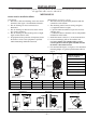
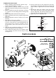
Single phase without
3-position switch
Single phase with
3-position switch
– 4 –
Figure 7
Figure 8
Figure 5
Figure 6
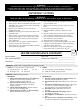
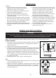
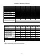
GENERAL
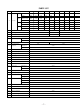
1. Use only copper conductors and approved Type 4X wiring
methods during installation. Refer to the “Technical Data” table
for the voltage, amperage and wattage ratings when sizing for the
appropriate conductors.
2. Supply voltage is to be within 10% of the data plate voltage.
3. External over-current protection is required and must meet data
plate ratings for voltage, amperage and frequency.
FIELD WIRING
1. Heater is supplied with an enclosure that has 2 standard
3/4" trade size conduit openings to accommodate the line conductors or
external thermostat connection.
2. Heater may be supplied with a factory-installed built-in room thermostat.
On heaters not supplied with this option, a remote thermostat is required.
Connect the remote thermostat conductors to the terminal block marked
T1, T2 and Ground. Any thermostat used with this heater must be:
a) Listed or Approved
b) Type 4X rated*, and
c) Rated at 120 volt minimum and 5 amp minimum.
*An appropriate Type 4X rated room thermostat is available from
the factory.
FINAL INSPECTION
1. Before application of electrical power:
a) check that all connections are secured and comply with the applicable
code requirements,
b) confirm that the supply voltage is compatible with the data
plate specifications,
c) remove any foreign objects from the heater,
d) ensure all external fittings and enclosure covers are secured,
e) ensure that the fan rotates freely, and
f) if equipped, ensure manual reset high-limit has been reset.
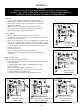
Figure 4
TRANSFORMER
120V
TEMPERATURE
HIGH-LIMIT
ELEMENTS
REDUNDANT
CONTACTOR
ELEMENT
CONTACTOR
OPTIONAL
PILOT
LIGHT
T1
T2
ROOM
THERMOSTAT
FAN DELAY
2
1
3
NO
NC
MOTOR
OPTIONAL
DISCONNECT
SWITCH
G
G
FIELD CONNECTIONS
L1
L2 L3
Three phase with
3-position switch
208, 240, 480 volt three phase models
without 3-position switch
Three phase without
3-position switch
600 volt models