
Manual

INSTALLATION
The installation instructions provide a general guideline for the installation and wiring of the heater.
All applicable codes must be adhered to.
MECHANICAL
– 3 –
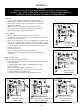
B dia.
DISCHARGE
GRILL
1/2" UNC
MOUNTING
HOLE
POWER SUPPLY
CONNECTION
2.3"
(59 mm)
C
A
D
(227 mm)
11.3"
8.9"
(287 mm)
F
(51 mm)
3.8"
(97 mm)
(190 mm)
7.5"
E
OPTIONAL DOOR INTERLOCKING
DISCONNECT SWITCH
13"
(329 mm)
14.6"
(370 mm)
2"
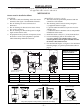
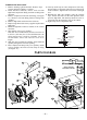
Minimum clearances for
service and airflow:
Front - 72" (1829 mm)
Back - 6" (152 mm)
Right Side - 10" (254 mm)
Left Side - 1" (25 mm)
Top - 8" (203 mm)
Bottom - 72" (1829 mm)
CEILING MOUNT
WALL MOUNT
45° MAX
AIRFLOW
Heater can be mounted
up to a 45° angle.
Using factory-supplied mounting bracket (included with each heater).
Customer-supplied bracket
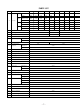
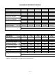
DIM. A B C D E F
3 to 10kW
12.5" (318 mm) 12.8" (325 mm) 8.5" (216 mm) 24.4" (620 mm) 6.4" (162.5 mm) 0.9" (23 mm)
15 and 20kW
12.1" (307 mm) 16.7" (425 mm) 7.5" (190 mm) 23.4" (595 mm) 8.4" (212.5 mm) 1.2" (30 mm)
25 to 39 kW
12.1" (307 mm) 20.7" (525 mm) 7.5" (190 mm) 23.4" (595 mm) 10.3" (262.5 mm) 1.3" (32 mm)
Figure 1
Figure 3
Figure 2
Heaters must be installed as follows:
LOCATION
1. The heater’s inlet and discharge areas must not be
obstructed. See figure 1 for minimum clearances.
2. The air discharge is not to be directed at a
thermostat.
3. The air discharge is directed across areas of heat
loss, such as windows.
4. The air discharge is directed along and at a slight
angle toward exterior walls.
5. If equipment freeze protection is important, locate
the heater as close to the equipment as possible
while maintaining minimum clearances.
MOUNTING
(see figures 2 and 3)
1. The heater must be permanently mounted with the
control box at the bottom.
2. The mounting surface must be strong enough to:
a.) support the heater’s weight,
b.) provide sufficient stiffness to prevent excessive
vibration, and
c.) withstand abusive situations such as transportable
installations of the heater.wiring of the heater must
3. Install the heater at least 6 ft. (1.8 m) from the floor.
4. Louvered discharge grill can be rotated in 45°
increments.
Heater only complies with U.S. Coast
Guard regulations when the grill is installed such that
the airflow is directed downward.
5. For maximum tilt angles, see figure 3. For maximum
mounting height, see general specifications table on
page 9.
(3 to 20kW
units only)