
User manual CC_SHBR12


Cc-Smart Technology Co., Ltd
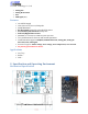
General information
Control Signal
Pin
Signal Description I/O
1 +5V 5V, 250mA Output Power O
2 AN Analog Input I
3 IN1 PWM/RX/PPM/ANA_JOY I
4 GND Ground of control signal I
5 IN2 DIR/TX/3V3 I/O
6 ENA Status and Reset I/O
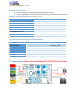
POWER and MOTOR Connection
Pin
Signal Description I/O
1 Vin- Ground of the auxiliary power supply I
2 Vin+ 8-40V power supply I
3 Ma Motor negative connection O
4 Mb Motor positive connection O
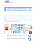
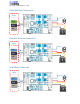
PWM Bi Direction Mode Connection:
PWM 0-48%
Velocity 0 =>Vmax (forward)
PWM 50-100%
Velocity 0 => -Vmax (reverse)
PWM
GND
MCU