
User manual CC_SHBR12

Cc-Smart Technology Co., Ltd
Current (A) Minimum wire size (AWG)
10 #20
15 #18
20 #16
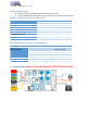
System Grounding
Good grounding practices help reduce the majority of noise present in a system. All
common grounds within an isolated system should be tied to PE (protective earth) through
a ‘SINGLE’ low resistance point. Avoiding repetitive links to PE creating ground loops,
which are a frequent source of noise. Central point grounding should also be applied to
cable shielding; shields should be open on one end and grounded on the other. Close
attention should also be given to chassis wires. For example, motors are typically supplied
with a chassis wire. If this chassis wire is connected to PE, but the motor chassis itself is
attached to the machine frame, which is also connected to PE, a ground loop will be created.
Wires used for grounding should be of a heavy gauge and as short as possible. Unused
wiring should also be grounded when safe to do so since wires left floating can act as large
antennas, which contribute to EMI.
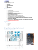
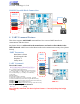
Power Supply Connection
NEVER connect power and ground in the wrong direction, because it will damage the
driver. The distance between the DC power supply of the drive and the drive itself should
be as short as possible since the cable between the two is a source of noise. When the
power supply lines are longer than 50 cm, a 1000µF/100V electrolytic capacitor should be
connected between the terminal “GND” and the terminal “+VDC”. This capacitor stabilizes
the voltage supplied to the drive as well as filters noise on the power supply line. Please
note that the polarity can’t be reversed.
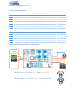
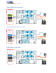
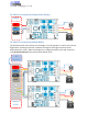
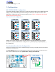
It is recommended to have multiple drivers to share one power supply to reduce cost if the
supply has enough capacity. To avoid cross interference, DO NOT daisy-chain the power
supply input pins of the drivers. Instead, please connect them to power supply separately.