
User manual CC_SHBR12

Cc-Smart Technology Co., Ltd
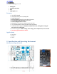
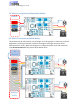
Indication:
RUN LED Blinking Description (when MCU Reset or Changing the Mode)
1 PWM 50/50 Mode
2 PWM DIR Mode
3 ANA/DIR Mode
4 UART Command Mode
5 RC (PPM signal) Mode
6 Analog Joystick Mode
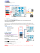
ERR LED Blinking Description
1 Under/Over Voltage
2 Over Temperature
3 Over Current
4
No RC signal is detected or the pulse width is out of acceptable range.
iOVER LED ON/OFF Description
OFF The iLIMIT Soft Switch don’t touch
ON The iLIMIT Soft Switch touched
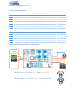
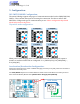
7. ENABLE/STATUS Pin Feature:
The ENA Pin is special PIN with Input and out-put ability.
This Pin will pull up to 5V by the driver after Reset state. And pull down if there are any error. The
user can read state of this Pin to know the status of driver.
The user can also Reset the driver by config the MCU Pin is a output Pin and set this Pin to GND
about 0.5 second and reconfig MCU Pin as input pin to read the status of the driver.
Please reconfig the MCU pin to input after forced Reset the driver
If you don’t need to know the status of the driver or reset the driver by MCU, please let it is free.
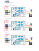
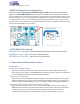
8. Recommendation:
Wire Gauge
The smaller wire diameter (lower gauge), the higher impedance. Higher impedance wire
will broadcast more noise than lower impedance wire. Therefore, when selecting the wire
gauge, it is preferable to select lower gauge (i.e. larger diameter) wire. This
recommendation becomes more critical as the cable length increases. Use the following
table to select the appropriate wire size to use in your application.