Cc-Smart Technology Co., Ltd User’s Manual For CCS_SHB12 Smart H-bridge Revision 1.0 ©2024 All Rights Reserved Attention: Please read this manual carefully before using the driver! Cc-Smart Technology Co., Ltd 1419/125 Le Van Luong, Phuoc Kien Commune, Nha Be District, Ho Chi Minh City, Viet Nam. Tel: +84983029530 Fax: No URL: www.cc-smart.net E-mail: ccsmart.net@gmail.
Cc-Smart Technology Co., Ltd The content in this manual has been carefully prepared and is believed to be accurate, but not responsibility is assumed for inaccuracies. Cc-Smart reserves the right to make changes without further notice to any products herein to improve reliability, function or design. Cc-Smart does not assume any liability arising out of the application or use of any product or circuit described herein; neither does it convey any license under its patent rights of others.
Cc-Smart Technology Co., Ltd UART Parameter ...................................................................................................................................... 9 UART Command: ....................................................................................................................................... 9 5. Configuration: ....................................................................................................................................
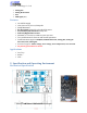
Cc-Smart Technology Co., Ltd Analog/Dir Analog Bi-Direction Uart PPM signal (RC). Features 10-40VDC Supply 12A Continuously Current, 30A peak. 300W Maximum. Bi-directional control for a brushed DC motor. Acceleration/Deceleration modify able. Soft Left/Right Home sensor MOSFETs are switched at 16 KHz for quiet operation. Two push buttons for fast test and manual operation. Communication support: PWM/Dir, PWM Bi-direction, Analog/Dir, Analog Bi- Direction, Uart, PPM signal.
Cc-Smart Technology Co., Ltd Elimination of Heat Driver’s reliable working temperature should be <100℃ It is recommended to mount the driver vertically to maximize heat sink area. Electrical Specifications (Tj = 25℃ /77℉ ) Parameters MSDI Min. Typical Max. Unit Peak Output Current 0 30 A Continuous Output Current(*) 0 12 A Power Supply Voltage +8 +40 VDC VIOH (Logic Input – High Level) 2 28 V VIOL (Logic Input – Low Level) 0 0.8 V +5V Output Current 250 mA Analog Pin (AN) 0 3.3 V ENA Pin 0 4.
Cc-Smart Technology Co.
Cc-Smart Technology Co.
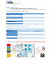
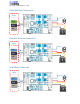
Cc-Smart Technology Co., Ltd RC Mode 1 Connection (Independent Mode): Receive +5V PPM GND RC Mode 2 Connection (Mixed Mode): The RC Mixed mode will combine two H-Bridges to work together to control two Left and Right Motor resulting in forward, backward, turning left and right movement of the differential drive robot. When two Bridges are configurated in RC mode and connected with RC-Extension PCB. They will in the RC Mixed mode.
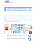
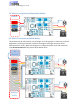
Cc-Smart Technology Co., Ltd ANALOG Joystick Mode Connection: JOYSTI VRx GND VCC 4. UART Command Feature: This driver support ASCII UART command line. User can use UART interface to communicate with the driver. Any Smart Driver is addressed in the manufacture and work as Slave Mode in the UART Network.
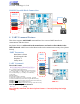
Cc-Smart Technology Co., Ltd 5. Configuration: DIP SWITCH MODE Configuration: The smart H-Bridge support many type of communication method such as PWM/DIR, PPM, UARTs,...They combine the input Pin to saving the connection. The Driver will use DIP SWITCH to config witch type of communication you use. Please configuration Dip Switch Mode before turn on the power. Dip switch mode configuration: 1. PWM 50/50 1 2 3 4 2. PWM/DIR 1 4. UART 1 2 2 3 4 3. ANA/DIR 1 5.
Cc-Smart Technology Co., Ltd iLIMIT Soft Home Sensor Configuration: The driver support Electric Current Home Sensor inside to limit the moving left and right. It is called iLIMIT SWITCH. The user don’t need add more extended limit switch. The driver will monitor the current when the Motor is running, if the current of the Motor same as with the iLimit (iLimit is a current limit setting by Variable Resistors in PCB) that mean the mechanical is touched.
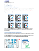
Cc-Smart Technology Co., Ltd Indication: RUN LED Blinking 1 2 3 4 5 6 Description (when MCU Reset or Changing the Mode) PWM 50/50 Mode PWM DIR Mode ANA/DIR Mode UART Command Mode RC (PPM signal) Mode Analog Joystick Mode ERR LED Blinking 1 2 3 4 Description Under/Over Voltage Over Temperature Over Current iOVER LED ON/OFF OFF ON Description The iLIMIT Soft Switch don’t touch The iLIMIT Soft Switch touched No RC signal is detected or the pulse width is out of acceptable range. 7.
Cc-Smart Technology Co., Ltd Current (A) 10 15 20 Minimum wire size (AWG) #20 #18 #16 System Grounding Good grounding practices help reduce the majority of noise present in a system. All common grounds within an isolated system should be tied to PE (protective earth) through a ‘SINGLE’ low resistance point. Avoiding repetitive links to PE creating ground loops, which are a frequent source of noise.