
Installation Sheet

Go to page 3
2
PAGE
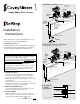
4 Install the SofStop mechanism.
Note: For Twin (Soft Open & Soft Close)
mechanism, go to instruction 10, overleaf.
If the pocket frame has been supplied with head jambs
fitted, remove the jamb from one side to allow access to
carriages for mounting and vertical height adjustment.
Refix the head jamb once door has been mounted and
desired door clearance is achieved.
Screw fix pocket
header into lintel/
stud when using
heavy doors
Clearance 3/8”-
13/16” (adjustable)
1 3/8”
Lintel
Head
top
approx. 3/8” clearance
Timber
pelmet
block
Head jamb
(supplied unfixed)
Fix after door
installation
Head jamb
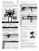
Single Action Soft Close
Pickup
mechanism
Tow
bar
Front
carriage
Dolly
wheel
M5 pan head
machine screw
Rear
carriage
Tow bar receiver
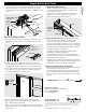
The SofStop mechanism fits together as shown:
SofStop
cassette
Rear carriage
Notched
end of
track
Sofstop cassette
2
1
Front carriage
SofStop
cassette
Notched end
of track
4 To load the SofStop mechanism into the track:
a) First, slide the rear carriage in from the notched end of
the track. Note: Rear carriage does not have a tow bar.
b) Insert the cassette into the notched end of the track, dolly
wheel first, ensuring that the pickup mechanism is facing up.
c) Slide the front carriage into the track with the tow bar
facing into the pocket.
Notched
end of track
Front
carriage
Hanger
bolt
SofStop
cassette
M5 pan
head
machine
screw
d) Secure the carriage to the cassette with the M5 pan head
machine screw. Tighten with a #2 Phillips drive.
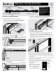
5 Hang the door(s).
Position the carriages in the pocket opening approximately
where the mounting plates on the door will be located when
the door is in the closed position.
Slide the door over the T Guide and into the pocket.
Align the mounting plates with the hanger bolts of the
carriages.
6 Adjust the door height.
When adjusting door height, the wrench should be
horizontal to the nut.
Use the small end of the wrench supplied to rotate the
hexagonal nut at the bottom of the carriage hanger shaft.
To raise door: Rotate wrench from left to right.
To lower door: Rotate wrench from right to left.
Note: The top of the hanger shaft screws into a self-locking
nut. If the hexagonal nut is turned counter clockwise too far,
the shaft will become loose from the self-locking nut. If the
turning resistance suddenly feels much easier, you have gone
too far.
Mounting
plate
Raise the door up so that
the round head of the wheel
hanger shaft lines up with
the keyhole shaped hole in
the mounting plate.
Depress the plunger using
the wheel hanger shaft head
and slide sideways until it
snaps into locked position.
Repeat for the other
carriage.
4
© Cavity Sliders USA Inc.
Drawings are not to scale.