
Installation Sheet

Striker
face plate
11
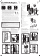
11. Position the striker face plate in the
centre of the striker body - this may need to
be adjusted in the steps following. Insert the
striker face plate screws and loosely tighten.
12. Close the door. When the striker is fitted
correctly the magnet will draw the plunger
forward. If this does not happen the striker is
misaligned with the plunger (see below). If the
alignment is correct, tighten the screws and
skip to Step 14; otherwise continue to Step 13.
✗✗ ✓
12
13
Striker
face plate
screws
2.5mm
(3/32”)
2.5mm (3/32”)
Plunger
13. The striker allows 2.5mm (3/32”) of
adjustment in each direction when the striker
face plate is fitted in the centre of the striker
body.
To adjust the face plate position, loosen the
striker face plate screws slightly and adjust the
face plate up or down to allow the plunger to
penetrate the striker face plate. If the plunger
still fails to penetrate the striker face plate, the
door height may need to be adjusted.
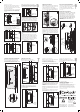
14. Manually push the plunger forward until
there is no gap between spring reservoir one
(SR1) and spring reservoir two (SR2).
Restrain the plunger nut using the large end
of one of the two identical supplied spanners.
SR1 SR2
No gap
14
Turn
clockwise
15
15. Place the small end of the second spanner
across the flats under the head of the plunger.
Keep the spanner restraining the plunger nut
stationary while turning the second spanner
clockwise. Continue to turn the spanner until
there is no longer a gap between the spanner
and the shroud face.
Front View Rear View
16. If installing a snib/snib or a snib one side
privacy handle proceed to Step 17, otherwise,
fit the emergency release button (with the
spring attached) over the locking slider arm.
16
Emergency
release
button
Emergency
release
button
Locking
slider arm
Front
flange
17. Fit the remaining side handle to the
chassis by sliding the front flange of the
handle under the heads of the 3x side handle
to chassis screws. Tighten the screws.
18. Fit the privacy face plate to the
chassis using the 3x face plate screws.
Face plate
screws
Privacy
face
plate
8. Remove the striker from its box. Remove
the striker face plate from the striker body.
Insert the 2x striker nuts into the recess in the
back of the striker body.
Insert the 2x striker face plate screws through
the slot in the front face of the striker body
and into the striker nuts. Loosely tighten the
screws.
Striker nuts
Striker
nuts
Rear View
Striker body
Striker
body
Striker face
plate screws
Striker
mounting
wood screws
10
Striker face
plate screws
9. Insert the striker body, with the striker face
plate screws and the striker nuts attached,
into the cut out in the closing jamb.
Striker
face
plate
screws
9
10. Remove the striker face plate screws.
The striker nuts are now trapped in position.
18
5
7
6
8
PAGE
PAGE
PAGE
PAGE
Fitting Emergency Release
Adjusting the Plunger
Fitting the Remaining Side Handle
Fitting the Face Plate
Striker face
plate screws
8
Screw the 4x striker mounting wood screws
into the closing jamb.
© Cavity Sliders Limited.
CAVILOCK
®
CL400
®
MAGNETIC (O.D. 2013)
ADA PRIVACY INSTRUCTIONS.
61230/CL405ZA925 - 02.2018
All copyright and other property in this document is reserved
by Cavity Sliders Limited. Details and specifications are
subject to change without notice. Whilst all care is taken
to ensure the accuracy of all information, no responsibility
will be accepted for any errors or omissions. ® CS FOR
DOORS, CS CAVITY SLIDERS and CAVILOCK are Registered
Trademarks. Patents pending.
Plunger
nut
Plunger
flats
Shroud
face
Red
section
Note: the locking slider arm may have been
pre-cut depending on the width of the door.
The drawing below demonstrates a cut
slider arm.
Cavity Sliders Limited
Auckland Head Office
5 - 7 Rakino Way
Mt Wellington
Auckland, NZ
T +64 9 276 0800
F +64 9 276 2525
info@csfordoors.co.nz
Recyclable
Packaging
www.csfordoors.co.nz
www.cavitysliders.com.au
www.cavitysliders.com
Push
here
➟
Gap
No
gap
Fitting the Striker
19. With the pull handle in the ‘unlocked’
position, insert one of the handle joining
screws through the bottom hole in the side
handle and tighten.
Fixing the Side Handle
Fixing the Side Handle
20. Close the door and push the pull handle
down into the ‘locked’ position.
Insert the second handle joining screw
through the top hole and tighten.
While the door is closed, lock and unlock the
door to check the action. Adjust if necessary.
21. With the pull handle down in the ‘locked‘
position, insert the RED clip-in indicator into
the TOP hole.
Note: the indicator is designed to remain in
place permanently and may require some
force to insert.
Fitting the Clip-in Indicator
Warning: it is very important that you follow
the next instructions carefully as the clip-in
indicator cannot be easily removed once
installed.
Fitting the Clip-in Indicator
22. Lift the pull handle up to unlock it.
Insert the GREEN clip-in indicator into the
BOTTOM hole.
23. If installing a handle with snib both sides,
fit the clip-in indicators to both sides.
Now turn the spanner anti clockwise
half a turn. The plunger should now be
adjusted correctly. Slide the door closed
to check that it latches. If the snib button
is hard to push down or the plunger
doesn’t engage with the striker, adjust as
necessary.
Pull
handle
Pull handle
in locked
position
Pull handle
in unlocked
position
Red clip-in
indicator
Green
clip-in
indicator
Handle
joining
screw
Handle
joining
screw
17
19
20
21
22