
Installation Guide

5
7
6
PAGE
PAGE
PAGE
Cavity Sliders Limited
Auckland Head Office
5 - 7 Rakino Way
Mt Wellington
Auckland, NZ
T +64 9 276 0800
F +64 9 276 2525
info@csfordoors.co.nz
Recyclable
Packaging
© Cavity Sliders Limited. CAVILOCK
®
CL400
®
MAGNETIC (O.D. 2013) PRIVACY BIPARTING INSTRUCTIONS.
60912/CL400ZA927 - 12.2014
All copyright and other property in this document is reserved by Cavity Sliders Limited. Details and specifications are subject
to change without notice. Whilst all care is taken to ensure the accuracy of all information, no responsibility will be accepted for
any errors or omissions. ® CS FOR DOORS, CS CAVITY SLIDERS and CAVILOCK are Registered Trademarks. Patents pending.
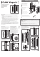
8
8. Remove the privacy chassis from its
packaging. Remove the face plate screw
and face plate from the chassis.
Align the chassis with the centre of the door
thickness. Screw the chassis to the door (using
the two chassis mounting screws) through
the slotted holes at the top and bottom of the
chassis. DO NOT fully tighten the screws.
Realign the chassis with the centre of the
door thickness. When happy with the chassis
position, fully tighten the screws.
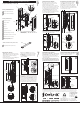
9
Component Drawings - Privacy Handle
Fitting the Privacy Handle
14. If installing a snib/snib or a snib one side
privacy handle proceed to Step 15, otherwise,
fit the emergency release button (with the
spring attached) into the two holes in the arm
of the locking slider.
Note: the locking slider arm may have been
pre-cut depending on the width of the door. The
drawing below demonstrates a cut slider arm.
14
Emergency
release
button
Emergency
release
button
Locking slider arm
15. Fit the remaining side handle to the
chassis and tighten the screws.
16. Fit the privacy face plate to the chassis
using the three handle face plate screws.
16
8
PAGE
www.csfordoors.co.nz
www.cavitysliders.com.au
www.cavilock.com
j
l
m
n
r
(2)
s (6)
t (3)
Privacy Side Handle (Left)
j
k
Privacy Side Handle Box
Privacy Side Handle (Right)
q (2)
p
o
u
v (2)
v
Plunger Adjustment Spanners (2)
Tools (contained in Privacy Chassis Box)
Note: Components will vary between the
‘Snib/Emergency’, ‘Snib/Snib’ and ‘Snib One
Side’ versions.
l
m
n
o
p
q
r
s
Privacy Face Plate
Privacy Chassis Box
Privacy Chassis
Plunger
Shroud
Plunger Nut
Spring Reservoirs (2)
Chassis Mounting Screws (2)
Side Handle to Chassis Screws (6)
Handle Face Plate Screws (3)
t
Emergency Release Button
(Where Applicable)
u
k
Front View
Reversed View
Rear View
Spring
(attached)
Two holes
Plunger
flats
Turn
clockwise
12
12. Place the small end of the second
spanner across the flats under the head of
the plunger.
Keep the spanner restraining the plunger
nut stationary while turning the second
spanner clockwise.
13
13. Continue to turn the spanner until there is
no longer a gap between the spanner and the
shroud face.
Now turn the spanner anti clockwise half a turn.
The plunger should now be adjusted correctly.
Slide the doors closed to check that they latch.
If the snib button is hard to push down or the
plunger doesn’t engage, adjust as necessary.
Plunger
nut
Gap
Spanner
Handle
face plate
screws
Face plate
3mm (1/8”)
gap under
head
Side
handle to
chassis
screws
9. Fit the six side handle to chassis screws.
Leave a 3mm gap (1/8”) between the underside
of the screw head and the chassis.
Centre of door
thickness
Correct alignment
✓
==
Slotted
hole
10. Fit the privacy side handle containing
the snib button to the chassis as follows
(if installing a snib/snib privacy handle
install ONE of the side handles only):
Front
flange
10
a
a
b
b
Locking
slider arm
Recess
Reversed View
11. Manually push the plunger in the privacy
chassis forward until there is no gap between
spring reservoir one (SR1) and spring
reservoir two (SR2).
Restrain the plunger nut using the large end
of one of the supplied spanners.
Push
here
➟
SR1
SR1 SR2
No gap
Gap
SR2
Adjusting the Plunger Fitting the Remaining Side Handle
a. Align the recess in the back of the snib
button with the arm of the locking slider.
b. Slide the front flange of the handle under
the heads of the three side handle to chassis
screws. Tighten the screws.
15
Chassis
mounting
screws
No
gap
11
IMPORTANT: Install THE OTHER handle FIRST
Fitting Emergency Release
Shroud
face