
Installation Guide
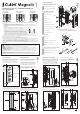

9. Close the door and mark a horizontal line
on the closing jamb 61.75mm (2-7/16”) down
from the top edge of the side handle.
Note: these instructions are demonstrated on
a recessed closing jamb, however, the same
method applies to a flat closing jamb.
32 40
32 40
40 32
40 32
2
3
7
C
L
5
4
6
Horizontal
line
Centre of closing jamb/
centre of door closing position
C
L
10
9
5
7
6
PAGE
PAGE
PAGE
Top edge of
side handle
61.75mm
(2-7/16”)
10. Open the door. Transfer the horizontal line
across the centre of the closing jamb. This
line represents the top of the striker cut out.
A double-sided striker cut out template has
been provided. Use the ‘RECESSED striker
template’ and instructions to router out the
recess in the closing jamb.
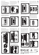
Striker nuts
Striker nuts
Rear View
Striker
face plate
screws
Striker body
12. Insert the striker body, with the striker
face plate screws and the striker nuts
attached, into the cut out in the closing jamb.
Screw the 4x striker mounting wood screws
into the closing jamb.
Striker
body
Striker face
plate screws
Striker
mounting
wood screws
Striker
face
plate
screws
13. Remove the striker face plate screws.
The striker nuts are now trapped in position.
Striker
face plate
Striker
face plate
screws
14. Position the striker face plate in the centre
of the striker body - this may need to be
adjusted in the steps following.
Insert the striker face plate screws and loosely
tighten.
15. Close the door. When the striker is
fitted correctly the magnet will draw the
plunger forward. If this does not happen
the striker is misaligned with the plunger
(see below).
✗ ✗ ✓
Striker
Plunger
17. Manually push the plunger forward until
there is no gap between spring reservoir one
(SR1) and spring reservoir two (SR2).
Restrain the plunger nut using the large end
of one of the two identical supplied spanners.
Push
here
➟
SR1
SR1
SR2
SR2
No gap
Gap
Striker
face plate
screws
2.5mm
(3/32”)
2.5mm
(3/32”)
16. The striker allows 2.5mm (3/32”) of
adjustment in each direction when the striker
face plate is fitted in the centre of the striker
body.
To adjust the face plate position, loosen
the striker face plate screws slightly and
adjust the face plate up or down to allow the
plunger to penetrate the striker face plate. If
the plunger still fails to penetrate the striker
face plate, the door height may need to be
adjusted.
Turn
clockwise
19. Continue to turn the spanner until there is
no longer a gap between the spanner and the
shroud face.
Now turn the spanner anti clockwise half a turn.
The plunger should now be adjusted correctly.
Check the action by sliding the door closed and
locking it using the key. Adjust if necessary.
Gap
No
gap
Spanner
18. Place the small end of the second
spanner across the flats under the head of
the plunger. Keep the spanner restraining
the plunger nut stationary while turning the
second spanner clockwise.
20. Fit the remaining side handle to the
chassis (using the 3x side handle to chassis
screws) by sliding the front flange of the
handle under the heads of the three screws.
Tighten the screws.
If the side handle contains a snib you will
need to align the recess in the back of the snib
button with the arm of the locking slider first.
Side
handle to
chassis
screws
Locking
slider arm
Reversed View
Front flange
21. If installing a ‘Key/Key’ handle you may
need to adjust the position of the locking
cylinder. To do so, insert the locking cylinder
Allen key through the slotted hole in the
chassis. Loosen the screw and slide the cylinder
into the desired position. Tighten the screw.
Handle
face plate
screws
Locking
face plate
22. Fit the locking face plate to the chassis
using the 3x handle face plate screws.
11
16
18
19
14
12
17
20
21
22
13
15
Plunger
flats
Locking
cylinder
Allen
key
Fitting the Striker
Fitting the Striker
Fitting the Remaining Side Handle Adjusting the Cylinder
Adjusting the Plunger
Fitting the Face Plate
Plunger
nut
11. Remove the striker from its box.
Remove the striker face plate from the
striker body. Insert the 2x striker nuts into
the recess in the back of the striker body.
Insert the 2x striker face plate screws
through the slot in the front face of the
striker body and into the striker nuts.
Loosely tighten the screws.
If the alignment is correct, tighten the screws
and skip to Step 17; otherwise continue to
Step 16.
Locking slider arm
Recess
Cavity Sliders Limited
Auckland Head Office
5 - 7 Rakino Way
Mt Wellington
Auckland, NZ
T +64 9 276 0800
F +64 9 276 2525
info@csfordoors.co.nz
Recyclable
Packaging
www.csfordoors.co.nz
www.cavitysliders.com.au
www.cavilock.com
© Cavity Sliders Limited. CAVILOCK
®
CL400
®
(O.D. 2013) KEY LOCKING INSTRUCTIONS. 60906/CL400ZA930 - 12.2014
All copyright and other property in this document is reserved by Cavity Sliders Limited. Details and specifications are subject to
change without notice. Whilst all care is taken to ensure the accuracy of all information, no responsibility will be accepted for any
errors or omissions. ® CS FOR DOORS, CS CAVITY SLIDERS and CAVILOCK are Registered Trademarks. Patents pending.
a
a
b
b
8
PAGE
Shroud
face