
Manual
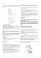
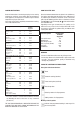

BUILTINDIMENSIONFOROVENWITHDOORTHICKNESSOF
20mm (dim B)
(dim B)
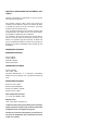
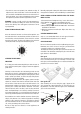
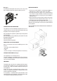
4.When installingmultipurposeovens installthe sshownin
gurenº6.
A. The support runner must be removed
B.Spacingof75-90mmbetweenthewallandtherearpartof
the support shelf and the base of the cupboard
C. Base
D. False box front to be assembled
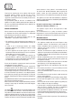
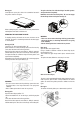
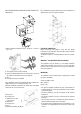
Fig. 7: Ventilation and gap requirements for the installation of e
simple electric oven in a standard cooking unit.
Minimum ventilation requirements for upper, base and support
shelves for the rear part of the unit.
A. Rear panel
B. Storage space
C. Remove the rear part
of this section
D. Real panel
E. Storage space
F. Base
G. Minimum ventilation gap 80 cm
2
Fig. 8: Ventilation and gap requirements for the installation of a
simple electric oven in an upper cupboard.
ELECTRICAL CONNECTION
Before connecting the appliance, check that the voltage
marked on the specifications plate coincides with the voltage
of the electricity network.
The NICEIC register is recommended for electrical installa-
tions.
WARNING – THIS APPLIANCE MUST BE EARTHED
This appliance must be wired to a 13 A bipolar automatic
switch with protected socket, which has a 3 mm separation
between contacts and is placed in an easily accessible place
next to the appliance.
IMPORTANT
The conductors of the network power supply lead are coded
by colours are follows:
Greenandyellow-Earth
Blue-Neutral
Brown-Live
•Thegreenandyellowconductormustbeconnectedtothe
terminal marked “E” or with the symbol of the earth or which
is green and yellow.
•The blue conductor must be connected to the terminal
marked “N”.
•The brown conductor must be connected to the terminal
marked “L”.
•The lead must not reach a temperature higher than 50 ºC
above the ambient temperature at any point.
•Ifthepowerleadisdamaged,itmustbereplacedbyaspe-
cialleadorunitsuppliedbythemanufactureroritafter-sales
service.