CASTLE INC Owner’s Manual TSM-35 Swing Front Heavy Duty Pocket Cutter
CASTLE, INC TSM-35 OWNERS MANUAL V1.
Table of Contents 1 INTRODUCTION.............................................................................................................................4 2 MACHINE SAFETY.........................................................................................................................5 2.1 SAFETY RULES ..........................................................................................................................5 2.2 INVENTORY .....................................................
1 Introduction Thank you for making the Castle TSM-35 the latest addition to your shop. Since 1985 our goal has been to manufacture and develop machines that make cabinetmaking and casework easier, faster and more profitable for the woodworker. This machine represents our commitment to your productivity. Castle machines are made in Petaluma, California and are manufactured to the highest standards using local vendors wherever possible.
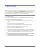
2 Machine Safety This machine was carefully prepared for shipment at our factory. Upon receipt of the machine, inspect for shipping damage. Report any damage IMMEDIATELY to the freight company, your Castle dealer and to Castle, Inc. DO NOT attempt to operate the machine if you observe any physical damage. Please contact Castle, Inc. at 800-282-8338 for instructions. 2.
2.2 Inventory CASTLE TSM-35 SWING FRONT HEAFY DUTY POCKET CUTTER HARDWARE PACK Part # Part Description Qty S90011 TSM-35 Operator Manual with Warranty Activation Card 1 T30465 Collet Wrench 1 T30466 Collet Wrench 1 G00234 Bit Gauge 1 S00350 Air Tool Oil for Sioux Drill 1 M00400 Castle Front Door, Black w/ Logo 1 D00720 Female Hinge 2 H00141 Door Handle 1 G00101 Door Spring Clip 1 F14125 ¼ - 20 x ¾ Bolt 1 CASTLE, INC TSM-35 OWNERS MANUAL V1.
2.3 Machine Requirements Electricity: 3-Phase 208VAC, 230VAC OR 460VAC Warning: See voltage tag on the machine or wiring diagram inside the voltage box to confirm the electrical requirements for your machine before wiring and running your machine. Caution: Always have a qualified electrician do any machine wiring. Shop Air Supply: 80 PSI minimum, 150 PSI maximum Dust Collection: The TSM-35 relies on motor cooling from dust collection. A 4” dust collection tube is located in the rear of the machine.
3 Setting Up Your TSM-35 Caution: Always use eye protection when operating power equipment. 1. Remove the machine from the pallet, position and secure your machine in its chosen location. Note: Holes in the base are for securing the machine to the floor. In some operations the machine should be elevated for better ergonomic operation but it still must be secured in place so that it cannot rock or tip. 2.
8. Check the rotation direction of the router before operation. The bit should turn counter clockwise. To check direction, start machine by pressing the green Start Button on the gray electrical box at the front of the machine. Press red Stop Button and look into the slot where the bit comes up to make the pocket. As the machine slows to a stop, notice the direction. Warning: Do not open the lid to check the direction as it will continue to turn for several seconds after the motor has been shut off.
4 Operating Instructions Caution: Always use eye and hearing protection when operating machinery. 1. With the air on and the Case Top down, press the green Start Button. Note: the red Stop Button must be in the “out” position before the Start Button will activate your machine. If the red button is pushed in, simply turn the button ¼ turn counter clockwise to release. 2. Place stock to be pocketed under the yellow Clamp Guard. 3.
5 Machine Adjustments Your TSM-35 comes factory-adjusted to handle typical pocket-hole needs. Some additional adjustment may be necessary after you have satisfied the air and electrical requirements explained above. Your pockets are adjusted at the factory for a 1 1/4” length screw. Note: For your safety, before making any adjustments please make sure that the red Stop Button is in the OFF position and both power and air are disconnected. 5.
3. Use a 7/16” wrench to loosen both of the ¼” hex head cap screws on the 7/8” x 2” plate. Note: Do not loosen more than ¾ of a turn. 4. Once both bolts are loose the plate can move forward and backward. By moving the plate toward the rear of your machine, your pocket will adjust for a shorter distance from the edge of your material. Moving the plate toward the front of the machine will adjust for a longer distance from the edge of your material. 5.
3. An aluminum Bit Gauge has been provided so that you may record the depth that is most suitable for your purposes. When optimum height has been achieved, set the edge of gauge on top of the router collet and score a line at the top of the bit near the mark “R” for router bit. 4. Tighten the collet, replace the wrenches and Bit Gauge in the proper slots in the white pallet; and close the Case Top carefully so as not to pinch your hand or fingers. The machine will not start while the Case Top is open. 5.
5.4 Pilot Drill Height Adjustment In some applications you may want to adjust where the pilot hole breaks through into the pocket. Castle recommends 5/16 of an inch from the surface of the material to the center of the pilot hole, but, for example, if you are cutting pockets in ½ inch material, ¼ of an inch from the bottom of the pocket is a better distance. Fig 4 1. Turn off Electrical power to your machine and raise the Case Top to its fully opened position. 2.
the pilot bit is the center of the hole provided in the case top. The following are instructions for adjusting where the centered position is. Fig 5 1. Turn off Air and Electrical power to the machine and raise Case Top to its fully opened position. 2. There are two Jacking Screws on each side of the machine. The bottom Jacking Screws are for the drill carriage. 3. Use a 7/16” wrench to loosen the ¼ -20 Nylock nut on each side of the machine. 4.
5.6 Left and Right Router Adjustment The ideal location for the router bit is to be directly in the center of the slot provided on the Case Top. If you find that the bit has moved to the left or right of the slot, your TSM-35 has a Left and Right Router Adjustment. Fig 6 1. Turn off Air and Electrical power to the machine and raise the Case Top to its fully opened position. 2. There are two Jacking Screws on each side of the machine. The top Jacking Screws are for the router carriage. 3.
5.7 Router Feed Speed Your TSM-35 is equipped with a Router Feed Speed Adjustment to allow you to cut pockets faster or slower depending on the material you are cutting. For example, if you are cutting soft wood, it may be better for your machine to cut faster to avoid having your bit spin in the material too long. This can cause the bit to heat up and become dull. In applications where you are cutting hard wood with your TSM-35, you may want to slow the speed at which your router cuts a pocket.
5.8 Drill Feed Speed Drilling into any material too quickly can cause your drill bit to break due to the force of impact. Drilling into any material too slowly can also cause your drill bit to break because it will heat up and lose its tempered strength. In order to prolong the life of your tooling, your TSM-35 is equipped with a Drill Feed Speed Adjustment. Fig 8 1.
5.9 Drill Delay Adjustment If you find that, in a particular application, your drill bit sticks in the material, a possible cause is that your drill has shut off before the drill bit exits the pilot hole. To test for, and fix this problem your TSM-35 is equipped with a Drill Delay Adjustment. Fig 9 1. Turn off Electrical power to your machine and raise the Case Top to its fully opened position. 2. Locate the Drill Delay flow control mounted next to the drill. 3.
retract, and the clamp does not release. In this situation you may need to readjust the Drill Stop Switch. Fig 10 1. Turn off Air and Electrical power to the machine and raise the Case Top to its fully opened position. 2. Under the red drill, you will find two cylinders. The cylinder on the left is the cylinder which drives the Drill Carriage. 3. On the Drill Carriage Cylinder there is a magnetic reed switch with a tensioning screw.
5.11 Router Stop Switch Much like the Drill Stop Switch, the Router Carriage also uses a magnetic reed switch to tell your TSM-35 when it has reached the end of its stroke for the router part of the cycle. In the event that this switch comes out of adjustment, your router will come up in the pocket and either return before reaching the end of the stroke, or the router bit will not return at all after cutting the pocket. The Sick switch is equipped with an orange LED when active. Fig 11 1.
6. Once touching 7 and 8, push the Router Carriage forward until it is approximately 1/16” away from the black bumper on the Router Cylinder and hold it in place. 7. Slide the Router Stop Switch until you read NO RESISTANCE and tighten the tensioning screw. Note: Over tightening this screw may cause the switch to fail. CASTLE, INC TSM-35 OWNERS MANUAL V1.
6 Definition and Description of Parts Clamp Cylinder: The large cylinder on the top of the machine acts as a clamp to hold the work safely in place during operation. This is a single acting, spring return, pneumatic cylinder with a padded foot on the end of the cylinder rod. The clamping force exerted is directly proportional to the amount of air pressure measured at the machine’s regulator. The Clamp Cylinder is secured by the Clamp Guard.
Drill Feed Speed: The Drill Feed Speed is the flow control valve located under the Case Top, near the back of the machine, left of center and can be seen through an access hole in the Safety Pallet. The Drill Feed Speed controls how fast the drill comes forward into the material. Web Adjustment Plate: The Web Adjustment Plate is under the Case Top, mounted at the rear of the white Safety Pallet, just to the right of center. The plate can be identified by the two bolt heads sitting on top of the plate.
Foot Pedal and Guard: The Foot Pedal is mounted inside a yellow metal guard and is connected to the machine by an electrical cord. The Foot Pedal will activate the machine cycle only if the Safety Buttons are depressed by the work piece. Safety Interlock Switch: The Safety Interlock Switch will automatically turn off the machine if the Case Top is opened while the machine is on. The machine will not turn on unless the Case Top is closed and the Interlock Key is in the switch.
Router Carriage: The Router Carriage is the red weldment located inside the machine and holds the Router Spindle and motor in place. This carriage is mounted to the machine with the upper two Jacking Screws which can be found on the side of the machine (one on each side). The carriage is moved back and forth through the rout cycle by a Drive Cylinder which links the carriage to the Web Adjustment Plate.
Indexing Brackets: The Indexing Brackets are located on the underside of the Case Top. The Indexing Brackets are used for quickly locating a pocket from the edge of the material. This is ideal for indexing face frame stock left and right for maximum productivity. Safety Buttons: Two small, silver/black button head screws project from the front of the machine under the Clamp Guard. The Safety Buttons push the Safety Blade, which then activates the Safety Switch, allowing the machine to cycle.
Jacking Screws: The Jacking Screws are located on both sides of the machine. The top Jacking Screws are for adjusting the Router Carriage left and right, and the bottom Jacking Screws are for adjusting the Drill Carriage left and right. Supplied Tools: Supplied tools are located on the front right side of the Safety Pallet. The tools provided with the TSM-35 are for servicing the machine’s tooling. CASTLE, INC TSM-35 OWNERS MANUAL V1.
7 Service and Maintenance Warning: Electrical hazard: Do not attempt to service Control Box components. Contact Castle, Inc. for the proper service information. 7.1 General To ensure productivity and longevity for your Castle Screw Pocket Machine, it is essential to follow a few simple steps. How often these steps are performed depends upon the number of hours the machine is operated each day.
Note: The model TSM-35 uses bearings that are pre-lubricated. No bearing lubrication is necessary. However, an automatic Lubricator is attached to the Air Regulator. Air tool oil must be kept in the Lubricator at all times. The Lubricator should be set so that a slight deposit of oil and dust occurs at the drill motor exhaust. The exhaust is located in front of the drill motor behind the drill motor collet. The oil / dust deposit should not occur until the machine has been run for at least 4 hours.
For use in plywood we recommend a two flute, carbide tipped bit. This leaves a clean cut and offers economically longer bit life. The pilot hole is made with a 9/64” drill bit, Part #B02964, which comes with the machine. Also available are a 7/64” and 3/16” size drill bit. Feel free to contact your local Castle Dealer or our Parts Department TOLL FREE at 800-282-8338 for information and pricing on tooling and accessory products for your TSM-35. 7.
7.4 Serial Number Log SERIAL NUMBER LOG MANUFACTURER PART NUMBER Castle, Inc. A00035 – TSM-35 Screw Pocket Cutter Sioux P01957 – Sioux SDG75S25FCT Motor Baldor E35551 – 1 – ½ HP TSM-35 Router Motor 230/460 V SERIAL NO. PURCHASE DATE: CASTLE, INC TSM-35 OWNERS MANUAL V1.
9. Warranty Information Castle, Inc. uses only the highest quality materials available for the construction of our machines. Your TSM-35 Heavy Duty Pocket Machine is warranted for one full year from the date of purchase against workmanship or material defects under normal use and service. We are not responsible for negligence, misuse or accidents. We suggest any and all machine maintenance or repair be discussed with an authorized Castle Representative prior to any disassembly.