
Operator Manual Owner's manual


CASTLE, INC TSM-21 OWNERS MANUAL V2.0 Page 33 of 41
• When the blade is raised a closed circuit should be registered (approximately 0 ohms). If an
open circuit is still registered, then the distance between the mounted assembly may need to
be reduced by
1
/
16
” on each side. Loosen the nuts holding the switch and magnet to the
case top then pinch them slightly closer and retighten the nuts.
• If this still doesn't fix the problem then a new switch assembly (magnet and reed switch)
should be installed.
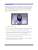
7.3 Foot Switch
Designed to work in series with the Safety Switch, the Foot Switch is a simple mechanical micro-
switch operated by a spring-loaded pedal. At rest the switch condition should be normally open.
Closing the switch begins the cycle.
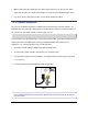
• Turn the power to the machine off.
• Turn the Foot Pedal and guard over and remove the two small screws that hold the pedal to
the base.
• Use a flat tip screwdriver to pry the pedal free from the yellow guard (it is held by a silicone
caulk).
• Using a flat or Phillips screw driver, remove the two screws on the left and right side of the
pedal. This will allow the pedal to come apart exposing the switch underneath.
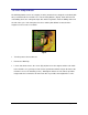
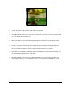
• Use two leads of the ohmmeter to probe the wire terminals while the switch is still in the
pedal. (Fig 25)
Fig 25