CASTLE, INC. Owners Manual TSM-21 Pocket Hole Machine CASTLE INC PO BOX 750236 PETALUMA CA 94975 WWW.CASTLEUSA.
CASTLE, INC TSM-21 OWNERS MANUAL V2.
Table of Contents 1 2 3 INTRODUCTION.............................................................................................................................5 1.1 DEFINITION OF TERMS ................................................................................................................5 1.2 IDENTIFICATION OF OPERATING FEATURES AND CONTROLS .........................................................6 1.3 MANUAL CONTENTS NOTICE ...............................................................
8 7.6 DRILL STOP SWITCH ................................................................................................................36 7.7 SERIAL NUMBER LOG ...............................................................................................................38 WARRANTY INFORMATION .......................................................................................................39 8.1 WARRANTY............................................................................................
1 Introduction Thank you for making the Castle TSM-21 Screw Pocket Machine the latest addition to your shop. Since 1985 our goal is to manufacture and develop machines that make cabinetmaking and casework easier, faster, and more profitable for woodworking professionals. This machine represents our patented screw pocket cutting technology. Castle machines are made in Petaluma, California and are manufactured to the highest standards using local vendors wherever possible.
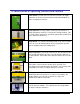
1.2 Identification of Operating Features and Controls Power Switch: Located on the left side of the machine, this toggle switch turns on the Pocket Router Motor and the Pilot Drill Motor as well as energizing the Controls. Clamp Cylinder: The large cylinder on the top of the machine is a clamp that holds the work piece safely in place during operation. This is a single-acting, spring-return, pneumatic cylinder with a padded foot on the end of the cylinder rod.
Motor Carriage: The Motor Carriage is the yellow, pivoting A-frame structure inside the machine. Both the Router Motor and the Drill Motor are mounted to this carriage. The forward and back carriage motion during the machine cycle is provided by the Drive Cylinder. Drive Cylinder: This double-acting pneumatic cylinder connected to the Motor Carriage and the machine case, moves the carriage through the routing and drilling phases of the cycle.
1.3 Manual Contents Notice This manual is not fully comprehensive. It does not and cannot convey every possible safety and operational problem which may arise while using this machine. The manual will cover many of the basic and specific safety procedures needed in a shop environment. We strongly recommend you visit our website (www.castleusa.com) and download the TSM-21 Diagnostic Manual for more comprehensive troubleshooting and repair information.
2 Machine Safety The Castle Model TSM-21 pocket machine was designed with operator safety as a priority. This machine was carefully prepared for shipment at our factory. Upon receipt of this machine, inspect for shipping damage. Report any damage IMMEDIATELY to the freight company, your Castle dealer and to Castle, Inc. DO NOT attempt to operate this machine if you observe any physical damage. If you detect any damage to your machine contact Castle, Inc. at 800-2828338 for instructions. 2.
8. Keep two hands on the work piece when initiating a pocket cycle on this machine. 9. Before attempting adjustments, maintenance, or repair, TURN OFF this machine, disconnect it from its power source and air supply. Wait for all motion to stop. Failure to disconnect this machine from its power source and air supply or wait for all motion to stop could result in electrocution or injury. 10. Always keep the area around this machine clean and uncluttered.
2.3 Machine Requirements Power Supply: 115 VAC ± 10%, 60 Hz, 20 Amp Service Warning: Do not use an extension cord. Using an extension cord to power your TSM-21 may void your warranty! Air Supply: 80psi (minimum), 150psi (maximum) 1.5cfm; Minimum ¼” ID air line Warning: Failure to provide an adequate supply of CLEAN, DRY air may void your warranty! Dust Collection: The TSM-21 will function better with proper dust collection attached. A vent for this purpose has been provided.
3 Setting Up Your TSM-21 Caution: • Always use eye protection when operating power equipment. Your Castle TSM-21 Pocket Cutter was set up and tested for proper operation at the factory. It is normal to find a small amount of sawdust in the TSM-21 from this process. • Verify that the Power Switch is turned off. Remove the Power Cord and Foot Pedal from inside the machine.
Warning: Do not introduce lubricants, oils, or solvents into the pneumatic system. Irreparable damage to pneumatic seals and components may occur. Using lubricants in the pneumatics of your TSM-21 may void your Warranty! • Inspect the T-Knobs and the U-Bolt on the carriage (Fig 3), making sure that the motors are secure and tight. Fig 3 • Fig 4 Using the wrenches located inside the rear of the machine make sure the router bit and the drill bit are secure in the respective collets.
3.1 Initial Configuration Now that the machine is connected to a power source and air supply, it is suggested that you test the machine’s controls for proper function. Caution: Read the Operator Manual carefully before operating. Make sure that you have followed all assembly and installation instructions correctly. Make sure that you are familiar with the functions described in the rest of the manual as well. Failure to follow this warning may result in serious injuries to persons and property.
• The Router Feed rate can be adjusted by using the flow control knob next to the air supply port (Refer to the Adjustment chapter on page 16). Turning it clockwise will reduce Router Feed rate, and turning it counter-clockwise will increase it. If the feed rate is too slow it can cause burning of the bit and burning of the pocket. If the rate is too fast it can cause the wood to shift. • Turn the Power Switch off when initial configuration is complete. CASTLE, INC TSM-21 OWNERS MANUAL V2.
4 Adjustments 4.1 Router Feed Rate Adjustment The Router Feed Rate Adjustment knob is located just under the air inlet port on the left side of the machine. (Fig 8) The adjustment knob only affects the cutting stroke of the pocket router. Fig 8 Turning the knob clockwise selects a slower Feed Rate. Turning the knob counter-clockwise selects a faster Feed Rate.
Note: If the work piece shifts noticeably during the Pocket Cycle, this usually means the Router Feed Rate is faster than the tooling’s ability to clear the Pocket. In general the desired Feed Rate is slower for harder, denser materials. 4.2 Pocket Web Adjustment The offset distance from the end of the pocket to the edge of the work piece is called the “Web.” (Fig 9) It has been factory set at approximately 7/8” to accommodate 1 ½” screws.
• Loosen the nylon locking nut. • To shorten the Web, slide the black Stop Plate toward the rear of the machine slightly. • To lengthen the Web, slide the plate toward the front of the machine slightly. Note: When the desired position has achieved, tighten the nylon locking nut securely to prevent shifting during operation. Subsequent adjustment of the Router Stop Switch may also be necessary (Page 31). 4.
4.4 Drill Feed Rate Adjustment The stroke speed with which the machine drills the pilot hole (and clamps the work piece) is solely a function of the air pressure set at the internal Pressure Regulator. There is no separate adjustment knob. Note: If the Drill Feed Rate is so fast that the machine shakes violently during the Pocket Cycle or if the Drill Feed Rate is so slow that the Pocket Cycle is significantly longer than two seconds, then it may be necessary to adjust the Pressure Regulator.
4.5 Pilot Drill Depth Adjustment The Pilot Drill operation works best when the drill depth is adjusted so that the drill bit just barely breaks into the pocket. If the drill bit extends farther than necessary, it can cause shorter bit life and over-size holes. The drill bit is set at the factory for a length of approximately 1 13/16” from tip to drill motor collet (this is a suitable distance for the factory default 7/8” Web).
4.6 Pilot Drill Height Adjustment The position of the Pilot Hole can be raised or lowered slightly to accommodate various thickness in work pieces or various pocket depths. • On the sides of the machine case, secure the Carriage Centering Screw with a 1/8” allen wrench. Loosen - but do not remove - the nylon lock nuts securing the set screw of the Motor Carriage to the machine case.
• To raise the pilot hole, slide the plate upward one or two hole positions (each hole position equals 1/16” of drill position). To lower the pilot hole, slide the plate downward. • Reattach the nut and bolt in the new hole position, and secure in place. • Tighten the nut on the plate that is nearest to the carriage axle. • Repeat for the other side.
5 Operation Caution: Read the Operator Manual carefully before operating. Make sure that you are familiar with the functions described in the rest of the manual as well. Failure to follow this warning may result in serious injuries to persons and property. Warning: • Always use eye protection when operating power equipment. With the Power Switch turned off, check to see that the carriage moves freely by hand and returns to the neutral position (Fig 17).
• Turn the Power Switch on (Fig 19). • Place the work piece to be pocketed on the Work Top. Slide it under the Clamp Guard and firmly push it against the face plate of the machine to press the Safety Buttons. (Fig 20). • Be sure to keep your hands clear of the clamp, then press and release the Foot Pedal to activate the cutting cycle. • The pocket will be cut at the point directly under the center of the Fig 19 Clamp Cylinder.
6 Service and Maintenance 6.1 Tool Changes Caution: Do not attempt to change tooling with compressed air power supplied to the machine! You do not need to remove the Work Top to change the bits, but removal of the Work Top will give access to the Router Motor and facilitate the removal of the Trimmer Motor. To change the Pocket Router Bit or the Pilot Drill Bit without removal of the Work Top, you will need to remove the respective motors from the carriage. 6.
• Allow the motor to drop into your left hand, then lift it out the rear door and change the tooling. • When re-installing, slide the motor through the curve of the U-bolt. Make sure that the motor’s power cable is pointing toward the front-right corner of the machine, and that the motor’s brush screw “ears” are in line perpendicular the case sides. • Push the Router Motor fully toward the top of the Motor Carriage. Make sure that the motor contacts the angled tabs on the yellow carriage (Fig 22).
6.3 Pilot Drill Bit • Open the rear door and unplug the drill motor. NOTE: Removal of the Work Top will facilitate the removal of the Drill Motor by making it easier to access and loosen the U-Bolt Top Nut and the black T-Knob. • Locate the Drill Motor U-Bolt Top Nut and loosen with a 7/16” wrench. Do not remove nut. (Fig 23) • Locate the black T-Knob to the left of the drill motor at the top of the carriage (Fig23). Loosen the T-Knob, but do not remove.
• Ensure that the Router Bit and the Drill Bit are clean, sharp, and undamaged. • Keep the Router and Drill Motors free from dust build up. Check for proper Safety Switch function. Turn the machine on and press the Foot Pedal without a work piece against the Safety Buttons. The machine should not cycle if the Safety Buttons are not pressed. If you suspect a Safety Switch malfunction, contact a Castle, Inc. Support Technician at 1-800-282-8338 as soon as possible for corrective.
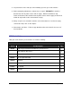
Note: Failure to clean sawdust from your machine may void your Warranty! Castle provides premium versions of the Router Bit and Drill Bit in the TSM-21 as standard equipment from the factory. Castle recommends these bits for all applications: Part No Part Description Function B00338 Solid Carbide, 3/8” Rough Mill, Three Flute Bit Routs pocket – Works in all materials, especially particle board, plywood, MDF, Melamine, etc.
7 Troubleshooting Warning: Electrical Hazard: Do not attempt to service Control Box components. Contact a Castle Support Technician for proper service information. 7.1 Dry Cycle Test Dry Cycling is an extremely useful troubleshooting technique if your Pocket Machine’s performance and cycling sequence seem irregular or questionable. It affords the opportunity to closely observe the mechanical, electrical, and pneumatic systems without routing pockets or drilling holes.
Scan with QR reader to watch. Total elapsed time: approximately two seconds. Or view on the web at - http://tinyurl.com/kdgsfvl 1. If the cycle does not begin, inspect the Power Switch, the machine power cord, the Safety Switch (page 33), or the Foot Switch (page 34). Make sure that your air supply is connected to the machine and inspect the internal Pressure Regulator (page 35). 2.
7.2 Safety Switch The Safety Switch on the TSM-21 consists of a magnet (no wires) mounted near a magnetic reed switch (with wires). (Fig 24) When the Safety Buttons are pushed by the work piece, they raise an L-shaped metal blade that rests between the reed switch and the magnet inside the machine. The assembly is wired in such a way that when the blade is raised the switch closes allowing electricity to flow to the Foot Pedal. Fig 24 • Turn the power to the machine off.
• When the blade is raised a closed circuit should be registered (approximately 0 ohms). If an open circuit is still registered, then the distance between the mounted assembly may need to be reduced by 1/16” on each side. Loosen the nuts holding the switch and magnet to the case top then pinch them slightly closer and retighten the nuts. • If this still doesn't fix the problem then a new switch assembly (magnet and reed switch) should be installed. 7.
• Without depressing the spring plate, the switch should register as an open circuit. When depressing the plate, the switch should register as a closed circuit (approximately 0 ohms). • If an open circuit is still registered, then a new switch should be installed. 7.4 Pressure Regulator The Pressure Regulator determines the Drill Feed rate and overall speed of the machine. It’s important that at least 80 PSI is going into the machine from the compressor.
7.5 Router Stop Switch The Router Stop Switch consists of a magnet (no wires) mounted near a magnetic reed switch (with wires) on the Router Stop Plate. At the full extension of the routing stroke, a tab on the Motor Carriage interrupts this switch to signal the start of the drilling stroke. If the clamp doesn’t release and the pilot drill hasn’t come out, then the Router Stop Switch may require a simple adjustment.
7.6 Drill Stop Switch The Drill Stop Switch consists of a magnet (no wires) mounted near a magnetic reed switch (with wires) mounted inside the machine case near the Safety Buttons. (Fig 28) At the full extension of the drilling stroke, the carriage interrupts this switch to signal the end of the drilling stroke and the end of the cycle. If the clamp doesn’t release and the pilot drill won’t retract, then the magnet is too close to the reed switch. Fig 28 • Turn the power to the machine off.
Fig 29 • Turn on the power to the machine and make a test pocket. • If the drill still stalls in the pocket, loosen and remove the screws that secure the magnet and the reed switch to the machine case. • Make sure that the side of the magnet housing with the notch in it is facing away from the reed switch. This ensures that the magnet is as far from the reed switch as possible. • If there is no notch in the housing, then detach it from the machine and visually inspect it.
7.7 Serial Number Log SERIAL NUMBER LOG MANUFACTURER Castle, Inc PART NUMBER SERIAL NO. A00022 – TSM-21 Pocket Hole Machine Robert Bosch Co. E21610 – Bosch PR10E 1.0 HP Motor Robert Bosch Co. E21617 – Bosch 1617 2.25 HP Motor PURCHASE DATE: CASTLE, INC TSM-21 OWNERS MANUAL V2.
8 Warranty Information 8.1 Warranty Your Castle Machine is warranted for one (1) full year from the date of purchase against workmanship or material defects under recommended use and service. Castle, Inc. is not liable for failures or injuries due to negligence, misuse, alteration, unauthorized service, or accidents. Castle, Inc., at its sole discretion, will elect to either repair or replace a machine (or machine component) that is found to be defective.
8.2 30-Day Refund Policy Any Castle machine may be returned by the End User, for any reason within 30 days of the purchase date for a full refund. Upon approval by Castle, Castle will initiate an RMA (Return to Manufacturer Authorization) and arrange for the return of the machine to Castle’s factory. Upon receipt of the machine Castle will issue a full credit to the Dealer (including any freight charges incurred).
8.4 Warranty Part Replacement 8.4.1 New product (within 30 days) • Castle is obliged to provide replacement parts at no charge. • Castle is obliged to ship overnight if requested by End User. 8.4.2 30 days to 12 months • Castle is obliged to provide replacement parts at no charge. • Castle is obliged to ship UPS 2-day if requested by End User. • If needed next-day, the End User will be charged to cover difference.