Castle Screw Pocket Machine Model TSM-21 with Mead Valves Operator Manual Castle, Inc. Petaluma, CA 800-282-8338 U.S. Patent No.
Table of Contents Safety Notification_______________ Machine Inventory_______________ Machine Requirements____________ Setting Up______________________ Operating Instruction_____________ Machine Adjustments Router Feed Rate Adjustment____________ ___ Drill Feed Rate Adjustment_________________ Pilot Drill Depth Adjustment________________ Pilot Hole Height Adjustment_______________ Pocket Depth Position__________________ ___ Pocket Distance Adjustment_____________ ___ Changing the Bits on your Machine ______
DO NOT ATTEMPT TO OPERATE THIS MACHINE UNTIL YOU HAVE READ THIS MANUAL. Safety Notification WARNING: The Castle Model TSM-21 Pocket machine was designed with operator safety as a priority. This machine was carefully prepared for shipment at our factory. Upon receipt of the machine, inspect for shipping damage. Report any damage IMMEDIATELY to the freight company, your Castle dealer and to Castle, Inc. DO NOT attempt to operate the machine if you observe any physical damage. Contact Castle, Inc.
Inventory With your Castle machine you should have received the following: Warranty Card (Please fill out & mail to Castle, Inc.
Setting Up Your TSM-21 Always use eye protection when operating power equipment. Your Castle TSM-21 pocket machine was set up and tested for proper operation at the factory. It is normal to find a small amount of sawdust in the TSM-21 from this process. Verify that the power switch is turned off. Remove the power cord and foot pedal from inside the machine. Remove the brass elbow from the black urethane hose by pushing the floating ring towards the elbow and pulling the hose at the same time.
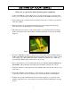
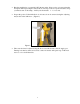
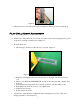
Plug the machine into a grounded 110V 20-amp outlet. Place a piece of scrap against the face plate while depressing the safety buttons, and step on the foot pedal. Be sure to keep your hands clear of the clamp. A full cycle should take 1 - 1 ½ seconds. Inspect the pocket. If the drilled hole is off center, it can be centered using the adjusting nut just below the drill motor. (Figure 2) Figure 2 The router feed rate is adjusted using the flow control knob next to the air supply port.
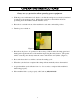
Operating Instructions Always use eye protection when operating power equipment. With the power switch turned off, check to see that the carriage moves freely by hand and is returned to the neutral position. Neither the router bit nor the drill bit should be protruding from the machine with the machine at rest. Place the foot switch in front of the machine in a safe and comfortable position. Turn the power switch on. Figure 3 Place the work piece to be pocketed on the worktop.
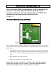
Machine Adjustments The Castle model TSM-21 is designed for use on a wide variety of materials. You will find that the machine performs well in hardwoods, softwoods, melamine, particleboard and MDF. The machine will work on materials of thickness from ½” to 1 ¾”. Router Feed Rate Adjustment Figure 4 When switching between materials of different density, it may be necessary to adjust the pocket router feed rate to achieve optimum performance. In general the desired feed rate is slower for harder materials.
Drill Feed Rate Adjustment The speed the machine drills the pilot hole is set at the factory. This is a function of the air pressure set at the internal air regulator. The drill feed rate will be best when the air pressure is set at 85psi. Normally you won’t need to adjust the regulator. However, if your drill cycle slows down significantly over time an increase in the regulator setting will correct the situation. Do not increase air pressure beyond 85psi.
Figure 6 The plate has two sides that can be used as settings for different processes in the shop. Pilot Drill Height Adjustment On the sides of the cabinet box loosen but do not remove the nuts securing the pivot point of the motor carriage assembly to the cabinet box. From the back door: The carriage is mounted on into the case on a plate. (Figure 7) Figure 7 Begin by removing the nut and bolt for the plate on the right side that are closest to you.
Pocket Depth Position The pocket cutting bit is set at the factory to rout at optimal depth in material between 5/8” and 7/8” thickness. To rout ½” material it is easiest to place a 1/8” shim on the worktable and place your work piece over it. The optimal router setting is determined by seating the standard Castle Router bit (RM38, CUR-38 or RM-38C) as far down in the collet on the router as it will go and then using the bit guide provided to set the depth.
Figure 9 To adjust the web, locate the stop plate bolt on the rear right side of the yellow clamp guard on top of the machine. This is a black metal plate that extends up through the case top alongside the clamp guard. You will find a nylock nut that secures the black router stop plate to the clamp guard housing. Loosen this nut and slide the black stop plate toward the rear of the machine slightly to shorten the web. To increase the web, slide this plate toward the front of the machine.
Figure 10 When re-installing make sure the motor is pushed up all the way to seat flush with the tabs on the yellow carriage (if unsure remove table top to confirm location). If changing the bit on the drill, loosen the T-handle to the left of the drill motor and slide the motor out from the rear of the machine.
Description of Parts See above 1. Clamp Cylinder: The large cylinder on the top of the machine is a clamp to hold the stock safely in place during operation. This is a single acting, spring return pneumatic cylinder with a padded foot on the end of the cylinder rod. The clamping force exerted is directly proportional to the amount of air pressure received by the machine. The clamp guard secures the clamp cylinder. 2.
8. Drive Cylinder: This double acting pneumatic cylinder connects the motor carriage to the machine case and moves the carriage through the rout and drill cutting phases of the cycle. The cylinder rod extends to move the carriage to the rear of the machine, which brings the router up to cut the pocket. When the cylinder rod is withdrawn, the carriage moves forward and the pilot drill is extended to bore the pilot hole into the pocket. 9.
Maintenance WARNING! Electrical Hazard: Do not attempt to service control box components. Contact a Castle, Inc. service technician for proper service information. Machine The model TSM-21 requires very little maintenance. However, to ensure productivity and longevity of your Castle Pocket Cutting Machine, it is essential to follow a few simple steps. How often these steps are performed depends upon the number of hours the machine is operated each day.
Motors and Bits The life of the machine is directly related to the care of the motors used to cut the pocket and pilot hole. Because the motors are enclosed in the machine where they can over heat if used beyond their operating range, it is important that the maintenance guidelines provided in the Porter-Cable instruction manual be strictly followed. Periodically during operation, blow out the air passages on both motors with compressed air. Caution: always wear safety goggles when using compressed air.
Troubleshooting Machine will not start the cycle If you press on the foot pedal while your motors are on but the clamp isn’t coming down and the routers aren’t coming up, then you have failure in the footswitch or the safety switch. The air pressure may also be set too low or not attached correctly. Refer to the “pocket is being cut but no pilot hole” section for steps on how to reset the air pressure.
When the magnet is placed against the reed switch then continuity should be registered. If continuity IS registered then the distance between the mounted assembly needs to be reduced by 1/16 of an inch on each side. First, loosen the screws holding the switch and magnet to the mounting brackets. Squeeze them together and then tighten the screws to reduce the distance. If this still doesn't fix the problem then a new switch assembly (magnet and reed switch) should be ordered.
The clamp is releasing slowly If the machine cycles at a normal rate, but the clamp is releasing slowly then a few tests need to be run to determine a cause and a solution. Figure 14 The clamp cylinder airline may have developed a crimp or leak in the hose. Solution Steps: Using an alternative air source insert it directly into the push-in fitting on top of the clamp cylinder. Turn on and then off.
This small exhaust port can slip behind the metal plate of the control box and/or get debris stuck in the hole. Make sure that this port is clear and open and that the port is not stuck behind the sheet metal. If the solenoid fails or becomes blocked it will cause either a slow release of the stock or a lack of clamping pressure. Solution Steps: The clamp solenoid is the pneumatic switch that signals the pilot valve to send full pressure to the clamp cylinder, which provides the clamping action.
Put a board against one of the safety buttons and the hit the foot pedal. Air should now be flowing from the “air out” side of the valve. Repeat these steps a few times to ensure all contaminates are expelled, then insert remaining line back into the “air out” side of the valve Turn routers back on and cut a test pocket. The router comes up and cuts the pocket but the clamp doesn’t release If the clamp doesn’t release and the drill doesn’t come out then the router stop switch may have failed.
The pocket is being cut and the drill comes up but doesn’t finish the pilot hole There are two possible causes of this issue. Either a switch has failed or the air pressure driving the carriage has been compromised. To determine the cause of the problem, cycle the machine until it stalls out during the drill phase. Push the carriage by hand (you can access the carriage through the back door.) If the cycle finishes when pushed manually then you have an air pressure issue.
If continuity IS registered then the distance between the mounted assembly needs to be reduced by 1/16 of an inch on each side. The laminate strip on the front of the machine must be removed to access the screws that retain the switch. When installing the new switch it does not matter which side the red & black wire go to. The magnet is sealed into its housing closer to one side than the other.
Air Pressure Solution One Steps: Figure 19 The drill solenoid is an air switch that controls the flow of air to the drive cylinder. (Figure 19) The drive cylinder, in turn, provides the pressure to move the carriage (with the drill attached) through the cutting part of the cycle. If the air line becomes blocked the drive cylinder won't have enough pressure to pull the drill all the way (or potentially any of the way) through it's stroke.
Press the hoses firmly back into the push-in fittings. Identify and replace any leaking hoses or switches. Turn router motor switches back on. Solution Two Steps: The air pressure may need to be adjusted at the pressure regulator inside the control box. The air pressure from the regulator determines the drill feed rate and overall speed of the machine. The factory setting is 85 PSI.
Warranty Information Castle, Inc. uses only the highest quality materials available for the construction of our machines. Your TSM-21 Standard Duty Pocket Machine is warranted for one full year from the date of purchase against workmanship or material defects under normal use and service. We are not responsible for negligence, misuse or accidents. We suggest any and all machine maintenance or repair be discussed with an authorized Castle Representative prior to any disassembly.
Castle Model TSM-21 Standard Screw Pocket Machine "For Models with Serial Number 61036 and Below" Items Included with Machine Part No.
Drawing 2 of 4 - Case Assembly Item # Part # 1 P00215 P14414 2 Part Description Clamp Cylinder Cylinder,Spring Return,2" Bore,1.
Drawing 2 of 4 - Case Assembly Item # Part # 14 M21012 F02014 F14212 F01420 S21002 15 16 Rear Door Assembly Rear Door, Black Washer, 1/4 ID x 2 OD, ZP Carriage Screw, 1/4-20 x 1/2 ZP Nut, Nylon Lock, 1/4-20 ZP Label, Wiring Diagram Qty C21101 Safety Switch Blade Assembly M21016 Safety Switch Blade F10358 Screw,Button Head Socket,10-32x7/8 Bk Oxide 1 2 U21007 F14340 F01420 F01410 Router Stop Switch Assembly E10850 Actuator, Magnetic Strong and Switch, Magnetic Reed F08012 Screw, Pan Phillips Machine
Drawing 3 of 4 - Carriage Assembly Item # Part # Part Description Qty Item # 8 1 E27301 Drill Motor, P-C #7301 Laminate Trimmer 1 2 B00964 Castle Drill Bit, 9/64 Cobalt w/ 1/4" Shank 1 3 B00038 Rough Mill, 3/8 Dia.Four Flute Cobalt-RM-38 1 4 D50038 Collet Assembly, 3/8 PC #6902 1 5 E26902 Router Motor, P-C #6902 1-1/2 HP 1 Part # Qty H25061 Spring, Extension, .562 OD x 8.25 L x .062 Dia.
Drawing 4 of 4 - Control Panel Assembly Item # 1 Part # E11424 D81614 F63238 F63260 Part Description Transformer Assembly Transformer, 120V Primary, 24V Secondary Spade Lug, 16-14 AWG #8 Screw, Pan Phillips Machine, 6-32 x 3/8 ZP Nut, Lock Washer, 6-32 Kep ZP E21024 E21016 E22708 E22708 E22708 Control Board Assembly EL-21 Solid State Control Board Terminal Strip, 16 Pin Wire, 22AWG, 2 Strand, Grey Jacketed Wire, 22AWG, 2 Strand, Grey Jacketed Wire, 22AWG, 2 Strand, Grey Jacketed 2 Qty 1 2 2 2 1 1 22"