CASTLE INC Diagnostic Manual TSM-21
Table of Contents 1 INTRODUCTION .............................................................................................................................4 1.1 2 HOW TO USE THIS MANUAL ........................................................................................................5 DRY CYCLE TESTING 21.95 ...................................................................................................6 2.1 PURPOSE .........................................................................
5.20 DRIVE CYLINDER SQE (SUPER QUICK EXHAUST) VALVE 21.61 .................................................43 5.21 PILOT HOLE ALIGNMENT 5.22 FOOT SWITCH (NO) 5.23 RESETTING THE MACHINE 5.24 SAFETY SWITCH/SAFETY BUTTONS (NO) 5.25 TOOLING CHECK AND REPLACEMENT 21.83 .........................................................................49 5.26 AIR PRESSURE REGULATOR SETTING 21.90 ........................................................................51 5.27 REPLACING SOLENOID VALVES 5.
1 Introduction Thank you for making the Castle TSM-21 Screw Pocket Machine a vital part of your shop. The TSM-21 is designed for use on a wide variety of materials including hardwoods, softwoods, melamine, particleboard and MDF. This manual is intended for anyone working with, or performing maintenance or service on the TSM-21. If trouble occurs, in most cases one of the major components is either not starting its function or not completing its function.
1.1 How to Use This Manual 1. Closely observe the behavior of the machine noting which component is involved and when in the operational sequence the problem is occurring. 2. Go to Section IV-Diagnostic Descriptions, which is organized by the operational sequence of the machine. 3. Find the description which most closely matches the problem and systematically perform the Diagnostic Procedures listed, checking them off as you go.
2 Dry Cycle Testing 21.95 2.1 Purpose Dry Cycle testing allows observation of the TSM-21’s mechanical, electrical, and pneumatic functions without routing pockets or drilling holes. Caution: Careful observation is essential when troubleshooting or seeking Technical Support. 2.2 Dry Test TSM-21 1. Locate the ON/OFF switches on the Router and Drill and turn them both off, or unplug both motors at the Control Box outlet. 2. Connect air and power to the machine. Turn the machine’s MAIN Power Switch ON. 3.
If the cycle stalls with the drill extended or if the cycle skips over the drill stroke entirely, check the Drill Stop Switch: Procedure 21.43 If the complete cycle takes significantly longer than two seconds, check the Air Supply, the Pressure Regulator, and the Router Feed Rate: Procedures 21.92, 21.90 and 21.32 If the Dry Cycle is successful, but a regular cycle fails when routing actual pockets and drilling holes, check the Tooling, the Motor Operation, and the Drive Cylinder: Procedures 21.
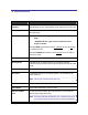
3 Definitions Term Definition Air Pressure Regulator Used to set the main operational speed of the machine. Factory set at approximately 75 PSI. / approximately 6 full clockwise turns from stop. Bar Spring Provides pressure to return the Motor Carriage to neutral after the Pilot Drill stroke. Continuity Testing “Visual Indicator” type testers use batteries and a light bulb. “Audible Indicator” type testers use batteries and a beeper or buzzer.
Solenoids Electrically controlled air valves which send pressurized air to the Clamp Cylinder and Drive Cylinder. See Appendix C & E for illustrations. SQE Super Quick Exhaust valves which release air pressure from the drive cylinder after the Router and Drill strokes. Note: Used up to machine SN: 62481 only.
4 Diagnostic Descriptions 4.1 Clamp Operation Page Procedure □ Check Clamp cylinder air line for leakage………………………… 19-20 21.12 □ Check Clamp Solenoid for blockage.……………………………… 17-18 21.10 □ Check Pilot Valve for function or blockage……………………….. (up to machine sn: 61076 Only) 22-24 21.14 Clamp doesn’t come down, but Machine Routs and Drills: Clamp comes down and STAYS DOWN as soon as air is attached…with Machine power OFF: □ Check Clamp Solenoid for function………………………………... 18-19 21.
Page Procedure □ Check Clamp cylinder and air line…………………………………. 19-20 21.12 □ Check Pilot Valve exhaust port…………………………………….. (up to machine sn: 61076 Only) 21-22 21.13 □ Check Pilot Valve for function or blockage……………………….. (up to machine sn: 61076 Only) 22-24 21.14 □ Check Clamp Solenoid for blockage………………………………. 11 21.10 □ Adjust internal Air Pressure………………………………………… 51-52 21.90 □ Check Pilot Valve for function or blockage……………………….. (up to machine sn: 61076 Only) 22-24 21.
4.2 Router Operation Page Procedure Router doesn’t cut pocket…Machine Clamps and Drills, but Clamp DOES NOT release: □ Check Router Feed Rate may be turned all the way down……... 31-32 21.32 □ Check Router Solenoid for function or blockage…………………. 30-31 21.31 □ Unclog Router Solenoid…………………………………………….. 29-30 21.30 □ Router Motor Operation…………………………………………….. 24-26 21.20 □ Check Router SQE Valve ………………………………………….. (or Solenoid exhaust port ) for leakage 43-44 21.
4.3 Drill Operation Page Procedure □ Check Drill Solenoid for function or blockage…………………….. 40-41 21.51 □ Unclog Drill Solenoid………………………………………………… 38-39 21.50 Drill DOES NOT come out, Machine Routs, Clamp DOES NOT release: Drill comes out and stays out as soon as air is attached…with Machine power OFF: Machine DOES NOT finish cycle when carriage is pushed forward by hand: □ Check Drill Motor is On……………………………………………… 33-34 21.40 □ Check Drill Stop Switch for function or adjustment……………….
Page Procedure □ Adjust air pressure, Machine cycling too fast …………………….. 51-52 21.90 □ Bit extended too far out of collet…………………………………… 34-35 21.41 □ Check Drill T-Handle bolt…………………………………………… 33-34 21.40 Drill bit breaking: 4.4 Overall Machine Operation and Pocket Adjustment Page Procedure Machine will not start cycle…motors are running: □ Check Air Supply, minimum 85 PSI required…………………….. 54 21.92 □ Check Safety Switch………………………………………………… 47-48 21.
Page Procedure □ Adjust Router Feed Rate, may be too fast………………………... 31-32 21.32 □ Check Clamp footpad, may need replacement…………………... 16 21.01 □ Check Tooling, may be dull………………………………………… 49-50 21.83 □ Adjust Router Feed Rate, may be too slow………………………. 31-32 21.32 □ Check Tooling, may be dull………………………………………… 49-50 21.83 □ Adjust Pilot Hole alignment…………………………………………. 45 21.72 □ Check Drill motor mounting………………………………………… 33-34 21.40 26-27 21.
5 Procedures 5.1 Clamp Foot Pad or Cylinder Replacement 21.01 5.1.1 TO REPLACE THE CLAMP FOOT PAD: 1. The Clamp Foot Pad is not attached by adhesive. While the Clamp Foot is still attached to the machine, use a flat blade screwdriver to remove the old Pad by carefully levering it out of its seat. 2. The rim of the new Pad must be bent and popped into place. Insert an edge of the new pad into the Clamp Foot and use a flat blade screwdriver to wedge the rest of the Foot Pad into the Clamp Foot. 5.1.
3. The Clamp foot can now be removed for replacement, or to allow for removal of the Clamp Cylinder assembly. 5.2 Unclogging the Clamp Solenoid 21.10 Note: All Solenoid Air Fittings are “Push In” connections. To remove an air line, push in the plastic or metal rim of the fitting and pull the air line out. To re-install, push the air line in until it meets resistance and then push in another 1/2'”. The appearance of the solenoids may differ.
5. Reconnect power and air to the machine, and turn the Power Switch ON. 6. Place a board against the Safety Buttons and depress the Foot Pedal. Air should now be flowing from the “Air Out” port of the solenoid. 7. Turn the Power Switch OFF and repeat steps 5 and 6 several times to ensure all contaminants are expelled, then reinsert the remaining hose back into the “Air Out” port of the Clamp Solenoid. 8. Turn the routers back on and cut a test pocket.
Clamp Exhaust Pilot Valve, up to SN: 61076 Clamp Solenoid Router Solenoid Drill Solenoid Regulator Knob Air OUT lines Air IN lines Router Feed Rate knob Fig 3 3. Reconnect the air supply to the machine and see if the router now actuates instead of the clamp. If it does the Clamp Solenoid has stuck open. 4. Swap the air lines back again. 5. Perform procedure 21.10, “Unclogging the Clamp Solenoid”. 5.4 Clamp Cylinder Check 21.
5.4.1 TROUBLESHOOTING STEPS: 1. Disconnect power and air from the machine. 2. Disconnect the air line from the “push in” fitting of the Clamp Cylinder. 3. Connect an external air supply directly to the “push in” air fitting. See Fig 4. Air Fitting Clamp Air line Clamp Cylinder Fig 4 4. The Clamp Foot should fully extend quickly. Remove the external air supply and the Clamp Foot should fully retract quickly. 5. If both clamp actions are smooth and quick the Clamp Cylinder is operating properly.
Air “OUT” line to Clamp Pilot Valve, up to Clamp Exhaust SN: 61076 Clamp Solenoid Air “OUT” line from Clamp Solenoid Fig 5 6. If the clamping and releasing actions are not smooth and quick, the Clamp Cylinder should be replaced. 5.5 Pilot Valve, Clamp Exhaust Check 21.13 This procedure applies only to machines up to SN: 61076. Air from the Clamp Cylinder is exhausted out of the Pilot Valve Exhaust port. This port is located to the left of the Air Pressure Regulator knob.
Air “OUT” line to Clamp Pilot Valve, up to SN: 61076 Clamp Exhaust Clamp Solenoid Air “OUT” line from Clamp Solenoid Fig 6 2. Make sure that this port is clear of debris and unobstructed by the sheet metal case. 5.6 Pilot Valve Check and Replacement 21.14 This procedure applies only to machines up to SN: 61076. The Pilot Valve provides full air pressure to the Clamp Cylinder. A leaking Pilot Valve can result in insufficient air pressure to the Clamp regardless of the Pressure regulator setting. 5.
Pilot Valve, up to Air “OUT” line to Clamp SN: 61076 Air “OUT” line from Clamp Solenoid Fig 7 2. When a cycle is started, air should now come out of the Clamp Solenoid’s output port. 3. Attach an independent air supply directly to the bottom hose controlling the Pilot Valve. The clamp should extend. 4. When the independent air supply is removed from the bottom hose the clamp should release. 5. If the clamp doesn’t extend, or extends but doesn’t release, or constantly exhausts replace the Pilot Valve.
7. Apply Teflon tape to the brass fitting still attached to the regulator. 8. Tighten the Pilot Valve onto the brass fitting. 9. Reattach the three plastic fittings and black hoses to the new Pilot Valve. 10. Put the plastic nut back on the regulator and tighten. 11. Re-install the Control Box using the carriage bolts. 12. Reconnect air and then power to the machine. 5.7 Router Motor Operation 21.20 The Router Motor has its own power switch located on the motor body.
Router U-Bolt Router T-Knob Router Motor Fig 8 3. Unplug the Router motor. 4. With your right hand loosen the Router T-Knob a few turns to provide enough slack to drop the Router Motor down into your left hand and then out the rear door. 5. When re-installing, make sure the motor face is pushed up to seat flush with the tabs on the yellow carriage (if unsure, remove table top to confirm location). 6. Tighten the black T-Knob onto the U-Bolt.
4. The Router Motor has two electrical brushes that should be periodically replaced. See Fig 9. Router Motor Brushes Fig 9 5.8 Adjusting the Web, Router Stop Plate 21.21 The space between the edge of the stock and the deepest part of the pocket is called the “Web”. The Web may be set between 5/8” and 13/16” by adjusting the Router Stop Plate from the top of the machine. The factory setting is approximately 7/8”.
Adjust towards front for Adjust towards back for longer web shorter web Router Stop Plate Lock Nut Fig 10 3. Adjust the Web length by loosening the lock nut and moving the Router Stop Plate towards the front of the machine for a longer web and towards the back of the machine for a shorter Web. 4. Secure the lock nut after making any adjustments. 5.9 Router Stop Switch (NC) 21.22 The Router Stop Switch consists of a magnetic reed switch (with wires) and a magnet (no wires).
the cycle to stall, or the router may not extend at all although the Pilot Hole Drill and Clamp finish the cycle. 5.9.1 TROUBLESHOOING STEPS: 1. Disconnect power and air from the machine. 2. The Router Stop Switch and Magnet are attached to the back side of the Router Stop Plate, which is located just to the left of the Drill motor. See Fig 11. Router Stop Switch Router Stop Plate Router Stop Magnet Fig 11 3.
8. If the switch continuously measures OPEN regardless how close the magnet is, replace the switch and magnet. 5.10 Unclogging the Router Solenoid 21.30 Note: All Solenoid Air Fittings are “Push In” connections. To remove an air line, push in the plastic or metal rim of the fitting and pull the air line out. To re-install, push the air line in until it meets resistance and then push in another ½” The appearance of the solenoids may differ.
7. Turn the Power Switch OFF and repeat steps 5 and 6 several times to ensure all contaminants are expelled, then reinsert the remaining hose back into the “Air Out” port of the valve. 8. Turn the routers back on and cut a test pocket. 9. Turn the Router Feed Rate valve clockwise while cutting test pockets, until the desired Router Feed Speed is reached. Note: If this procedure does not correct the problem, the Router Solenoid will need to be replaced. Refer to Procedure 21.
Pilot Valve, up to sn:61076 Clamp Exhaust Clamp Solenoid Router Solenoid Drill Solenoid Regulator Knob Air OUT lines Air IN lines Router Feed Rate Knob Fig 13 3. Attach the air supply to the machine and see if the drill now extends instead of the router. 4. If it does, the Router Solenoid has stuck open. 5. Swap the air lines back again. 6. Perform procedure 21.30 “Unclogging the Router Solenoid”. 5.12 Router Feed Rate Adjustment 21.
5.12.1 TO RESET THE ROUTER FEED RATE: 1. Locate the Feed Rate knob on the left of the case and fully loosen the Jamb Nut. See Fig 14. Router Feed Rate Knob and Jamb Nut FASTER SLOWER Fig 14 2. Rotate the Feed Rate knob fully clockwise until it stops. 3. Rotate the Feed Rate knob 2 full revolutions counter-clockwise. 4. This setting is typical for hard woods. 5. Adjust the Feed Rate to your material by ½ or ¼ turn at a time to obtain a clean, smooth pocket. 6.
5.13 Drill Motor Operation 21.40 The Drill Motor has its own power switch located on the motor body. This switch should always be in the ON position. Drill motor operation is controlled by the Power Switch on the machine. Warning: Do not run the motor for more than two hours at a time. The motor requires a ½ hour cool down period after each two hour period. The Drill Motor is attached to the Motor Carriage by a bolt that is secured with a black T-Knob.
5.13.2 REMOVING / INSTALLING THE DRILL MOTOR: 1. Disconnect power and air from the machine. 2. Unplug the motor. 3. With your left hand loosen the T-Knob until it releases the Drill Motor. Use your right hand to lift the motor back and then out the rear door. 4. When re-installing, make sure the motor mounting bolt aligns with the mounting hole at the top of the carriage. Make sure the drill’s power cable is pointing down. 5. Tighten the black T-Knob onto the mounting bolt. 6.
5.14.1 TESTING STEPS: 1. Hold the shank against a solid surface, and tap the end of the bit. 2. If the bit slides down into the shank AT ALL it needs to be replaced. 3. If the bit doesn't slide in the shank, hold the shank with pliers and with another pair of pliers; grip the bit BELOW THE FLUTE, just above where the bit joins the shank. Do not use excess grip pressure on the bit itself. Twist the bit and shank in two, opposite directions 4.
5.15 Drill Single Coil Bar Spring 21.42 The Bar Spring is located inside the top of the machine, above the Control Box. The Motor Carriage compresses this spring as it moves forward to drill the Pilot Hole. After the Pilot Hole is drilled, the Bar Spring provides the push to return the carriage to neutral position. If you push the carriage forward by hand it should “spring” back when released. If the carriage remains forward the Bar Spring may be loose or broken. 5.15.1 REPLACEMENT STEPS: 1.
6. Push the carriage forward by hand. The carriage should “spring” back when released. 7. Reinstall the Control Box and reconnect air and then power to the machine. 5.16 Drill Stop Switch (NC) 21.43 The Drill Stop Switch consists of a magnetic reed switch (with wires) and a magnet (no wires). The switch is Normally CLOSED (NC) and OPENS at the end of the Pilot Hole cycle when the Motor Carriage breaks the magnetic field.
3. Test for continuity across the terminals of the switch. The switch should be CLOSED with the Motor Carriage in neutral position. 4. If the switch measures OPEN while the Motor Carriage is in neutral position, adjust the magnet closer to the switch and repeat step 3. 5. Push the carriage forward until it makes contact against the Face Plate. The switch should now measure as OPEN. (A few kilo ohms of resistance are normal when the switch is OPEN.) 6.
“Push In” rim while pulling out air line Drill Solenoid Air OUT Line Air IN Line Fig 19 2. Reconnect air to the machine and the “Air In” line will now be flowing with about 85 PSI. Use the “Air In” line to clean out both open ports on the Drill solenoid. 3. Disconnect the air supply and reinsert the air line that was flowing, back into the “Air In” port of the solenoid valve. 4. Un-plug or turn off both routers. 5. Connect power and air to the machine, and turn the Power Switch ON. 6.
5.18 Drill Solenoid Check 21.51 The Drill Solenoid controls air pressure to the Drive Cylinder, which provides the forward motion of the Drill’s boring stroke. If the Drill Solenoid has stuck open, the drill will extend as soon as air is attached to the machine, regardless of whether the power is turned on. If the Drill Solenoid is clogged the Drill may not start or complete the pilot hole. The appearance of the solenoids may differ.
3. Attach the air supply to the machine and see if the router now extends instead of the drill. If it does then the Drill Solenoid has stuck open. 4. Swap the air lines back again. 5. Perform procedure 21.50 – “Unclogging the Drill Solenoid”. 5.19 Drive Cylinder Check 21.60 The Drive Cylinder provides the forward and back stroke to the Motor Carriage for the Router and Pilot Drill phases. If the cylinder fails or if the air lines become clogged, the machine may not complete one or both of these phases.
Drive Cylinder Router SQE Valve Drill SQE Valve Drill Solenoid line Router Solenoid line Fig 21 5. Cycle the machine a few more times to see if the situation can be repeated. 6. If the stalled Drive Cylinder consistently leaks air, the cylinder must be replaced. 5.19.2 OPTIONAL STEPS: Sometimes an air leak may be more noticeable during the Drill stroke. 7. Un-plug or turn off only the Drill motor. 8. Connect power and air to the machine, and turn the Power Switch ON. 9.
5.20 Drive Cylinder SQE (Super Quick Exhaust) Valve 21.61 The Drive Cylinder provides the forward and back stroke to the Motor Carriage for the Router and Pilot Drill phases of the cycle. If the Drive Cylinder mounted SQE (Super Quick Exhaust) valves fail or become clogged, the machine may not complete one or both of these phases. Test by rocking the carriage back and fourth by hand through the rear door. You should detect a “puff” of air at the SQE valves when manually rocking the carriage.
2. Un-plug or turn off both routers 3. Place two boards on opposite sides of the slot on the Table Top, press them against the Safety Buttons, and depress the Foot Pedal. 4. At the rear door, manually simulate the Router and Drill strokes by first pulling, then pushing the yellow Motor Carriage. 5. Make sure air escapes first from the Router Solenoid and then from the Drill Solenoid before the manual cycle is complete. 6. Reconnect the “Air Out” lines to the Router and Drill Solenoids. See Fig 22. 7.
5.21 Pilot Hole Alignment 21.72 The Pilot Hole should be drilled in the center of the deepest part of the pocket. 5.21.1 ADJUSTMENT STEPS: 1. From the rear door, locate the hex nut immediately below the Drill T-Knob on the upper left side of the Motor Carriage. See Fig 24. 2. Tightening the hex nut moves the drill tip left relative to the operator. Adjust accordingly. Misaligned Pilot hole Drill T-Knob Hex Nut Fig 24 5.22 Foot Switch (NO) 21.80 The Foot Switch is located in the Foot Pedal.
5.22.1 TESTING STEPS: 1. Turn the Power Switch OFF. 2. Remove the two small screws that hold the Pedal to the yellow guard. 3. Use a flat tip screwdriver to pry the Pedal free from the guard. It is secured by silicone caulk. 4. Use a flat or Phillips screwdriver to remove the two screws on the sides of the pedal and remove the top. See Fig 25. Spring Plate COM Terminal NC Terminals Fig 25 5. Test for continuity at the wired connections with the switch still in the pedal. 6.
5.23 Resetting the Machine 21.81 If the Power Switch is ON and the footswitch is pressed before the air supply is attached, the machine will begin to cycle as soon as the air is attached. This can result in the router bit becoming jammed against the Clamp Foot. 5.23.1 RESET STEPS: 1. Turn the Power Switch OFF. (This allows the solenoids to reset.) 2. Detach the air supply. (This allows the cylinders to reset) 3. Reattach the air supply. 4. Turn the Power Switch ON. 5.
Safety Switch Safety Switch Magnet Safety Blade Fig 26 3. Test for continuity at the terminals of the switch with the Safety Blade resting between the switch and the magnet. The switch should measure as OPEN. 4. If the switch measures CLOSED make sure the blade is resting squarely between the switch and magnet. Otherwise the distance between the switch and magnet may need to be increased by 1/16”. 5. When pressing the Safety Buttons, the switch should measure CLOSED.
5.25 Tooling Check and Replacement 5.25.1 21.83 ROUTER: 1. Disconnect power and air from the machine. 2. Open the rear door and unplug both motors. 3. To the right of the Drill Motor is the Router T-Knob that tightens a large U-Bolt holding the Router Motor in place. See Fig 27. Drill T-Knob Router U-Bolt Router T-Knob Fig 27 4. With your right hand loosen the Router T-Knob a few turns to provide enough slack to drop the Router Motor down into your left hand and then out the rear door.
7. Tighten the black T-Knob onto the U-Bolt. When the motor has been fully secured by the U-Bolt you might observe that the motor face is no longer flush with the yellow carriage tabs. That’s OK. 8. Manually rock the Motor Carriage toward the rear of the machine and make sure that the router bit cleanly fits in the slot on the table top. 5.25.2 DRILL: 1. Disconnect power and air from the machine. 2. Open the rear door and locate the Drill Motor at the top of the Motor Carriage.
5.26 Air Pressure Regulator Setting 21.90 The Pressure Regulator determines Drill Feed Rate, clamping pressure, and overall speed of the machine. The factory setting is approximately 75 PSI and should be checked periodically or when machine performance becomes rough or too slow. Cycles that are too slow can burn bits and cause drill bit separation at the shank. Cycles that are too fast can cause drill bits to break or to cut over-sized holes.
5. Cut test pockets and adjust slightly more or less than 6 turns until the appropriate operational speed is reached. NEVER EXCEED 7 FULL ROTATIONS. 6. Push in the click-collar on the Regulator knob to lock it. Note: If the Pressure Regulator has been adjusted, the Router Feed Rate may need readjustment after the Pressure Regulator setting has been finalized. See Procedure 21.32 5.27 Replacing Solenoid Valves 21.91 To replace a solenoid valve, follow the steps below. 5.27.1 STEPS 1.
4. Label the three solenoids and remove the two hex nuts and lock washers that hold the solenoids together. See Fig 31. Clamp Solenoid “Push In” rim while pulling out air line Router Solenoid Drill Solenoid Hex Nuts Air OUT Air IN Lines Fig 31 The appearance of the solenoids may differ. See Appendix E, page 51 for equivalent illustration for machines SN: 61076 and above. 5. Label then disconnect the "Air In" and "Air Out" lines of the solenoid to be replaced.
9. Reassemble the solenoids in a stack and tighten the hex nuts and lock washers. Do not over tighten the hex nuts. 10. Reinstall the Control Box using the carriage bolts. 11. Reconnect air and then power to the machine. 5.28 Attaching Air Supply 21.92 An air supply with a MINIMUM of 80 PSI must be provided for proper operation of the TSM-21 Pocket Machine. 1. From the operator’s position the air inlet is the 1/4” NPT fitting located on the left side. 2.
6 Appendix A – Machine Safety 21.80 It is your responsibility to ensure that you understand this procedure before performing the following tasks. Contact the document author if you have any questions about this procedure. 6.1 General Safety Rules for Machine Operators Read the Operator Manual carefully before operating this machine. It contains important information and warnings concerning the use and operation of this machine.
to stop. Failure to disconnect this machine from its air supply and power, or failure to wait for all motion to stop could result in electrocution or injury. When attempting any kind of electrical repair work, disconnect the machine from AC mains power. Always keep the area around the machine clean and uncluttered. Poor housekeeping could result in slips, falls or other injuries.
7 Appendix B – Wiring Diagram 21.
8 Appendix C – Control Box Works 21.
9 Appendix D – Solenoid, Pneumatic Diagram 21.
10 Appendix E – Control Box Works 21.
11 Appendix F – Solenoid, Pneumatic Diagram 21.
12 Appendix G – Index Page Section Air Pressure Regulator, Setting…………………………………………………. 51-52 21.90 Air Supply, Attaching……………………………………………………………... 54 21.92 Clamp Cylinder, Air Line Check……………………………………………........ 19-20 21.12 Clamp Foot Pad, or Cylinder Replacement……………………………………. 16 21.01 Clamp Solenoid, Function Check…………………………………………….…. 18-19 21.11 Clamp Solenoid, Unclogging……………………………………………………. 17-18 21.10 Control Box Works, Reference, Appendix C & E (Note Serial#)……..…. 58 & 60 21.
Page Section Resetting the Machine………………………………………………………….. 47 21.81 Router Feed Rate Adjustment…………………………………………………... 31-32 21.32 Router Motor Operation and Servicing ……………………………………....... 24-26 21.20 Router Solenoid, Function check……………………………………………….. 30-31 21.31 Router Solenoid, Unclogging……………………………………………………. 29-30 21.30 Router Stop Switch, normally closed (NC)…………………………………….. 27-29 21.22 Safety Buttons / Safety Switch, normally open (NO)…………………………. 47-48 21.