CASTLE, INC MORTISE MACHINE MODEL TSM-20 OPERATOR’S MANUAL Addendum Revised: December 16, 2010 (rev 2)
CASTLE, INC. MORTISE MACHINE MODEL TSM-20 OPERATOR'S MANUAL ADDENDUM TABLE OF CONTENTS Page # 1.0 SAFETY SWITCH CHECK ........................................................................................................... 1 2.0 AIR PRESSURE REGULATOR………………………………………………………………….2 3.0 SOLENOID MANIFOLD - CLEANING....................................................................................... 3 4.0 DRIVE CYLINDER SQE CLEANING......................................................................
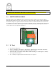
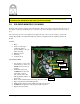
CAUTION: ALWAYS DISCONNECT POWER AND AIR BEFORE ATTEMPTING ANY MAINTENANCE OR TESTING ON YOUR CASTLE MACHINE! 1.0 SAFETY SWITCH CHECK The safety switch on the TSM-20 is a micro switch located on the outside of the control box (Fig 1). When the safety buttons at the rear of the worktop are depressed by the stock, they actuate a blade inside the machine that presses against the button of the micro switch.
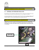
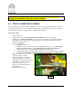
CAUTION: ALWAYS DISCONNECT POWER AND AIR BEFORE ATTEMPTING ANY MAINTENANCE OR TESTING ON YOUR CASTLE MACHINE! 2.0 INTERNAL AIR PRESSURE REGULATOR The internal air pressure determines the drill feed rate and the overall speed of the machine. The factory setting is 75 PSI. It is important for the machine function to have at 75 PSI to the machine. Locate the regulator in the control box (Fig 2). Unlock the yellow lock ring by pulling it slightly toward the black knob.
CAUTION: ALWAYS DISCONNECT POWER AND AIR BEFORE ATTEMPTING ANY MAINTENANCE OR TESTING ON YOUR CASTLE MACHINE! 3.0 SOLENOID MANIFOLD CLEANING Begin by removing the control box from the machine. This can be done by removing the four screws on the outside of the case and sliding the box out. Once out, remove the plate from the front of the control box. The coil located closest to the regulator in the upper left side of the control box (Fig 3) operates the Clamp.
CAUTION: ALWAYS DISCONNECT POWER AND AIR BEFORE ATTEMPTING ANY MAINTENANCE OR TESTING ON YOUR CASTLE MACHINE! 4.0 DRIVE CYLINDER SQE CLEANING The drill solenoid is an air switch that controls the flow of air to the drive cylinder. The drive cylinder, in turn provides the pressure to move the drill carriage through its cycle. If the air line becomes clogged the drive cylinder may not have enough pressure to cycle the drill completely. SOLUTION STEPS: 1. 2. 3. 4. 5. 6. 7. 8.
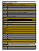
TSM-20 PARTS LIST Castle Part # Part Description Drill & Router Motors & Accessories Porter Cable 3102 Trimmer Motor (Drills hole) DISCONTINUED E23102 E26902 Porter Cable 6902 Router Motor (Routs pocket; mount with F14232 bolt) (same router as TSM-21) D50014 1/4" Collet Assembly (for E23102 motor) Note: Brass bushing no longer available; replaced by 1/4" shank on the bit D50031 Collet Nut Microswitches E60286 Snap-action Microswitch (Silver push button) (Drill Stop, Rout Stop, and Wood Sensor Switch) Note
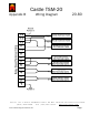
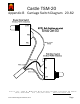
Castle TSM-20 Appendix B Wiring Diagram 20.80 Castle, Inc. 1364 N. McDowell Blvd. PO Box 750236. Petaluma CA 94975 (800) 282-8338 Fax (707)765-0953 www.castleusa.com Castle TSM-20 Diagnostic Manual, Rev.
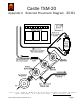
Castle TSM-20 Appendix B Carriage Switch Diagram 20.82 Castle, Inc. 1364 N. McDowell Blvd. PO Box 750236. Petaluma CA 94975 (800) 282-8338 Fax (707)765-0953 www.castleusa.com Castle TSM-20 Diagnostic Manual, Rev.
Castle TSM-20 Appendix C Solenoid Pneumatic Diagram 20.81 Castle, Inc. 1364 N. McDowell Blvd. PO Box 750236. Petaluma CA 94975 (800) 282-8338 Fax (707)765-0953 www.castleusa.com Castle TSM-20 Diagnostic Manual, Rev.