CASTLE INC Owners Manual TSM-12
CASTLE, INC TSM‐12 OWNERS MANUAL V1.
Table of Contents 1 INTRODUCTION.............................................................................................................................4 2 MACHINE SAFETY.........................................................................................................................5 2.1 SAFETY RULES ..........................................................................................................................5 2.2 INVENTORY .....................................................
1 Introduction Thank you for making the Castle TSM-12 the latest addition to your shop. Since 1985 our goal has been to manufacture and develop machines that make cabinetmaking and casework easier, faster and more profitable for the woodworker. This machine represents our commitment to your productivity. Castle machines are made in Petaluma, California and are manufactured to the highest standards using local vendors wherever possible.
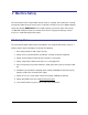
2 Machine Safety The Castle TSM-12 was designed with operator safety as a priority. This machine was carefully packaged for shipment at our factory. Upon receipt of the machine, inspect for shipping damage. Report any damage IMMEDIATELY to the freight company, your Castle dealer and to Castle, Inc. DO NOT attempt to operate the machine if you observe any physical damage. Contact Castle, Inc. at 800.282.8338 for instructions. 2.
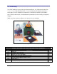
2.2 Inventory Your TSM-12 will pocket any material you would normally rout. It is designed for material from ½” to 1 ½”. Use of materials thinner than ½” is not recommended. Every TSM-12 machine is factory adjusted. If you should find a small amount of sawdust in the bottom of your TSM-12, please don’t be alarmed. This is an indication that your machine has been factory tested prior to shipping.
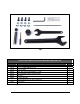
Fig 2 CASTLE TSM-12 BENCH-TOP POCKET MACHINE HARDWARE PACK Part # Part Description Qty F51628 5/16” - 18 Nuts 4 F44114 ¼ - 20 x 1” Flathead Machine Screws 4 F01420 ¼ - 20 Locknuts 4 B02964 9/64” TiN Coated Premium Drill Bit w/ ¼” Shank 1 B00338 3/8” Solid Carbide 3-Flute Premium Router Bit 1 D50038 3/8” Collet 1 B00622 6” Square Driver Bit 1 Bosch Collet Wrenches (for Bosch 2.0hp #1617) 2 T00532 --- 5/32” Hex Key 1 O00234 Bit Gauge 1 CASTLE, INC TSM‐12 OWNERS MANUAL V1.
2.3 Tools To complete assembly of Castle machine, you will require the following tools: (1) 7/16” wrench or ratchet (1) ½” wrench or ratchet Fig 3 2.4 Machine Requirements ELECTRICITY: Your TSM-12 is designed to run on a 110 volt -15 AMP standard 3 prong power supply. 2 prong power adapters are not recommended for use on this machine and could cause electric shock to the user. Be sure your unit is properly grounded.
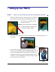
3 Setting Up Your TSM-12 Caution: Always use eye and hearing protection when operating power equipment. 1. Remove the machine from the carton and plastic over-wrap and place on its back as shown (Fig 4). Be careful to place it on a clean surface free of debris to avoid damage to the finish. Caution: Remove Foam pads from between the case sides and router carriage before running the machine (Fig 5). Fig 4 Fig 5 2.
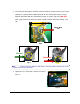
4. To install your drill motor it should be rotated so that the vertical feature on the motor cowling is in contact with the Motor Stop Tab on the small motor carriage. (Fig 8). Align the drill motor with the small motor carriage as shown. (Fig 9) You DO NOT want a gap between the tab on the motor carriage and the drill motor cowling. (Fig 10).
6. Unpack the Bosch #1617 router motor, collet wrenches and 3/8 collet. Remove router from base. DO NOT UNTIE THE POWER CORD! Replace the 1/2” collet with the 3/8” collet (from the hardware pack) onto the motor and insert the Castle Premium carbide router bit until it sits 1” above the top of the collet. Secure the router bit with the collet wrenches. Toggle the motor switch to the “ON” position. Fig 12 7. Install the router in the yellow carriage, carefully noting the orientation (Fig 13).
9. Inspect each motor cord to verify that they are plugged into the duplex power outlet box inside the machine and that they are clear of any moving parts. You may untie the main machine power cord at this time. Verify the router bit is positioned at the center of the cutout on the underside of the worktop (Fig 15). If it is not, refer to the Machine Adjustments section “Pocket Hole Alignment” before proceeding. Place the machine on your workbench right side up (Fig 16).
4 Operating Instructions 1. Check to be sure the switch on top of the machine is in the OFF position and then plug the TSM-12 into a 110 volt grounded power supply. 2. Place material to be pocketed on the work table under the clamp and squarely against the rear face. 3. Push forward on clamp lever (red handle). Confirm that the material is held securely in place (Fig 17), test by manually pulling on the material.
5. Push the black handle away from operator rapidly until it hits the stop (Fig 20). This routs the pocket. If you release the black handle, the machine will move to the neutral position on its own. It is not necessary to release the black knob before proceeding to step 6. Fig 20 Note: The first pocket you cut will create a through slot in the worktop. To insure a clean cut, make sure a work piece is securely clamped in place. 6. Pull black handle toward you rapidly until it hits the stop (Fig 21).
4.1 General Information The hand clamp should be tight enough for a “brisk” travel of both the routing and drilling strokes. If your material moves during the cycle, tighten the clamp slightly. Note: Bit “burning” (router or drill bits) is caused by either dull tooling, too slow of a movement of the operating lever or both. Your TSM-12 is powered by two high speed routers and is designed to aggressively enter the material being pocketed.
Included with your machine is a template for cutting out a cover for the bottom of your TSM-12, necessary for creating a vacuum for pulling dust and air out of the case. Using the template provided; cut out a cover for the hole in the bottom of the case from any 1/8” thick material. Fig 25 At the underside opening of the case, slip the clips (part # F11010) over the holes provided with the flat face of the clips facing out.
5 Machine Adjustments Your TSM-12 is factory adjusted to handle typical pocket-hole needs. Some adjustment may be necessary. Note: Before making any adjustments, please sure that the machine is disconnected from the electrical power outlet. 5.
5.2 Web Adjustment To move the pocket (routed portion) closer to, or further from, the edge of the material, use a 7/16” wrench and loosen the Nylock nut next to the operating handle (Fig 29). Moving the nut away from you will make the pocket cut closer to the edge of the material, pulling the nut toward you will make the pocket farther from the edge of the material. Tighten the nut each time before testing. This is a trial and error method until you get the pocket where it suits you best. Fig 29 5.
6 Service and Maintenance In order to ensure productivity and longevity for your Castle Bench-top Screw Pocket Machine, it is essential to follow a few simple steps. How often these steps are performed depends upon the number of hours the machine is operated each day. As a general rule, operators should visually inspect the machine at the start of each work shift in the following manner: 6.1 Router Bit Replacement 1. Unplug the TSM-12 from the electrical outlet. 2.
4. Re-install the router in the yellow carriage, carefully noting the orientation depicted below. With the motor firmly engaged against the carriage, tighten the locknuts with a 7/16” wrench and the bar knob alternating between both to ensure even tension on the U-bolt (Fig 32). Fig 32 6.2 Pilot Bit Replacement 1. Unplug the TSM-12 from the electrical outlet. 2. Loosen the hose clamp with a slotted screw driver (Fig 33), and pull the drill out of the machine. Fig 33 3.
4. To install your drill motor it should be rotated so that the vertical feature on the motor cowling is in contact with the Motor Stop Tab on the small motor carriage. (Fig 35). Align the drill motor with the small motor carriage as shown. (Fig 36) You DO NOT want a gap between the tab on the motor carriage and the drill motor cowling. (Fig 37).
Motors and Bits Because the motors are enclosed in the machine, it is important that the maintenance guidelines provided in the manufacturer’s instruction manual are strictly observed. Periodically during operation, blow out the air passages on both motors with 30 PSI compressed air. Let motors rest/cool down after 2 hours of continual use. Use dust collection for clearing sawdust out of your machine case and creating air flow through the case to aid in cooling the motors.
7 Warranty Information Castle, Inc. uses only the highest quality materials available for the construction of our machines. Your TSM-12 Bench Top Pocket Machine is warranted for one full year from the date of purchase against workmanship or material defects under normal use and service. We are not responsible for negligence, misuse or accidents. We suggest any and all machine maintenance or repair be discussed with an authorized Castle Representative prior to any disassembly.