LB-23 Diagnostic Solutions Index Air Pressure at Primary Regulator…………………………………………… 23.10 Air Pressure at Secondary Regulator………………………………….………23.40 Belt Adjustments……………………………………………………............... 23.65 Collet Adjustment…………………………………………………...……….. 23.21 Cutting Cycle-time Adjustment…………………………………………...…. 23.23 Electrical Supply Check……………………………………………………… 23.80 Foot Switch Mechanics………………………………………………………. 23.84 Head Lubrication……………………………………………………………... 23.01 Index Pin Setting & Resetting……………………………………...
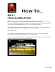
How To… 23.01 Head Lubrication The head should be oiled every 30 to 40 hours of usage. The head, once it is broken in beyond its initial start-up, should run very quietly with no loud metallic racket or grinding. In order to maintain the machine in good working order, the head should never be run dry. The head uses oil impregnated bushings that need to stay oiled for optimal performance.
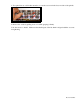
. Add 10 to 15 drops of oil to each of the holes. The oil is picked up by the wick and distributed evenly among the spindles 4. Locate the Drive Link Pins and add 1 or 2 drops of oil to each. The pins can be oiled once every 30 hours of usage. However, this should only be done if the head is in good adjustment, but still has a metallic rattle. 5. After the oil is added the machine should be left running for AT LEAST 30 minutes and then all excess oil wiped off.
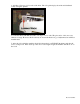
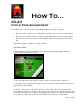
How To… 23.10 Resetting Air Pressure at the Primary Regulator The primary regulator is located on the right side of the machine, just below the tabletop. There are two regulators located in this spot. The primary regulator is located closer to the rear of the machine of the two. SOLUTION STEPS: 1. Setting internal pressure for the head can be achieved by turning the primary regulator counterclockwise until the knob stops. 2.
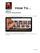
How To… 23.20 Tooling Check and Replacement The tooling for a Line Boring machine is designed to give maximum performance for an extended period of time. Typically, all the bits will need to be replaced at the same time, but occasionally individual bits will become damaged and need replacement. SOLUTION STEPS: 1. To check the tooling turn off the machine and lift up the yellow guard by pulling the plunger locks on either side of the guard. 2. Inspect all the bits.
3. To replace bits use a 3/32 allen wrench to loosen the set screw in the bottom collar of the spindle. 4. Remove the old bit by pulling down on it while grasping it firmly. 5. Do the reverse to install. Make sure that the flat part of the bit shank is aligned with the set screw for tightening.
How To… 23.21 Collet Adjustment There are two collets per spindle, making 46 collets per head. The collet on the bottom of the spindle is used to lock the drill bit into the spindle assembly. The upper collet is used to hold the entire assembly to the head. To get the best results the upper shaft collar should pushed as close to the snap ring as possible, and then tightened.
How To… 23.23 Cycle Time Adjustment Two adjustments control the amount of time that the cutting cycle takes to complete: 1. The air pressure to the head is set at the primary regulator closest to the rear of the machine. 2. The first valve activated in the foot switch is supplied with air from the secondary regulator, which is the one closest to the front of the machine. This, in turn, supplies air to the index pins. The primary regulator should be set at 80 to 85 PSI. SOLUTION STEPS: 1.
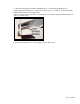
5. This can be checked by partially dismantling the foot switch and checking the foot switch spring against this photo to make sure the part is in good condition. It should retain the illustrated shape when not under pressure. * Please note that it is not necessary to dismantle the foot switch to the point illustrated here in order to view the spring. 6. If the pedal spring needs to be reset please see procedure 23.
How To… 23.40 Adjusting Secondary Regulator The secondary regulator is the one towards the front of the machine and controls pressure delivered to the index pins. It is called the secondary regulator. While there is no gauge to check the internal pressure driving the machine, there is an easy way to reset the regulator to factory settings. SOLUTION STEPS: 1. Turn the secondary regulator knob all the way to the left, counter-clockwise so that it is completely closed. 2.
How To… 23.42 Checking Index Pin Hoses The hoses that supply the air to the Index Pins run from the secondary regulator through the Guard Frame, and are visible when looking into the opening at the rear of the machine. If air pressure is unusually low despite adjustment at the regulator, it's a good idea to check these hoses as well as the fittings where the hoses connect into the cylinders. SOLUTIONS STEPS: 1.
2. When tracing the hoses, you should be looking for kinks or splits in the material. These are most likely to occur in places where the hoses run out of the machine and are open to being pinched. 3. If you trace the hoses all the way back to the Index Pin, then make sure that you have a firm connection at the barb that connects into the pins.
How To… 23.43 Adjusting the Indexing Pins If it appears that the pins are out of alignment, you can straighten them out by drilling a test board and realigning a Pin in one of the drilled holes. Follow the testing procedure to confirm they are out of alignment. TESTING PROCEDURE: 1. Use a scrap of at least two feet in length and cut a set of holes with the front Drop Gauge down. 2. Slide the board over so that either the left or right Index Pin can enter one of the holes that you just drilled. 3.
2. Use a piece of board to cut a full row of holes in. Make sure that there isn't much sawdust remaining in the holes. 3. Slide the board over so that the Index Pin will enter the last hole, but still leave the majority of holes underneath the head. 4. Bring the head down into the previous holes while watching very closely that the bits are entering in the exact center. 5. While the head is down place the Index Pin into the hole (if not already there), and tighten the nuts on the bracket.
How To… 23.60 Motor Check The machine uses an electrical motor that draws a great deal of amperage. If the motor isn't running then the following steps should be followed. SOLUTION STEPS: 1. Switch off the machine, make sure that it is plugged in. The machine should not be powered through an extension cord of more than six feet. 2. Switch the motor back on. 3. If the motor doesn't activate then try hitting the reset button on the side of the motor housing. 4.
5. Make sure that the pulley at the bottom of the motor shaft is spinning 6. If the pulley is not spinning, check the motor shaft to make sure that it is spinning. 7. If the above steps do not resolve the issue, then please contact Castle, Inc.
How To… 23.65 Checking the tension on the belt If the head significantly slows down or stops while you are drilling, then you may need to check the tension on your belt. TESTING PROCEDURE: 1. Make sure the machine is unplugged. 2. Reach through the rear of the machine and test the tension on the belt by squeezing it together. 3. It should be very difficult to get the belt sides to touch each other. If it is relatively easy to get the sides to touch then the belt is too loose.
SOLUTION STEPS: You will need another person to complete these steps. 1. Using a wrench, LOOSEN the four 5/16 carriage bolts that hold the motor and motor bracket in place. DO NOT REMOVE these bolts. 2. Use a 2x4 as a wedge and a 4x4 as a fulcrum. 3. Stand in front of the machine and pull the 2x4 towards your body in order to create enough tension on the belt. Do this while someone else tightens the four carriage bolts. 4.
How To… 23.70 Table Top Adjustment The table top is adjustable in relation to the guard frame and head. There should be between a 1/8 " and a ¼ " gap with wood in place. If it is greater then this, the table needs to be adjusted in order for a proper depth hole to be cut. SOLUTION STEPS: 1. Locate and LOOSEN the three brackets that lock the table into position. There is one bracket in front and one on each side underneath the table. The brackets are held in place by 9/16" hex head nuts.
2. Once the table is loose, locate the four leveling bolts. There are two on each side of the machine on the underside of the table. 3. Adjust the bolts up or down and check that the table is level and has the appropriate clearance from the guard. 4. It is important to maintain the table in the same level position it was in before the adjustment. To do this, the leveling bolts must be turned the SAME NUMBER OF TURNS AS ONE ANOTHER.
How To… 23.71 Adjusting the Wing Table The wing tables fold out on either side of the table top to extend the work surface. The adjustment for the wing table is inside the body of the machine. Another person will be needed for this adjustment. SOLUTION STEPS: 1. Open the front door of the machine. 2. Locate the nuts that secure the wing table arm to the case side.
2. Using a 9/16" wrench, LOOSEN the nuts while someone else holds the wing table in the desired position. 3. Once the proper position has been achieved, tighten down the nuts. 4. Repeat for the other side.
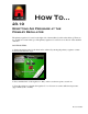
How To… 23.80 Power loss during drill cycle If the machine is experiencing power loss during the drill cycle the following items will need to be checked. If either is found to exist, it is possible that the amperage of the machine is falling too low to allow proper operation of the machine. SOLUTION STEPS: 1. If you are running the machine off of an extension cord, it must be AT LEAST 14 ga. and it must be no longer than 6 feet. 2.
How To… 23.82 Adjusting the depth of the head The travel limiter controls how far down the head can move towards the table top and into the stock. If your holes are not deep enough or they are too deep you may need to make an adjustment to the Travel Limiter bolt. SOLUTION STEPS: 1. Locate the 1/2" hole just left of center in the bit cover on the top of the machine. You'll know you have the right hole because when you look in it there will be a large phillips head screw inside. 2.
How To… 23.84 Foot Switch Test The foot switch has two micro-switches and a spring inside the pedal. In order for the pedal to function properly the spring needs to contact the first valve before the second. This sends the Index Pins down before the drill head. When the pedal is released the spring should completely back off of the valves. SOLUTION STEPS: 1. Make sure the machine power is off and the air is still connected. 2.
4. Remove the nylock nut while holding the screw tightly and remove the pedal spring. 5. With the spring out of the pedal, bend the spring about 1/8" whichever direction it needs to be adjusted. 6. Re-assemble the pedal being careful to tighten the spring retaining, 6/32" nylock nut ONLY to the point that the screw tip is flush with the nylon. 7. Attach the pedal guard to the pedal and test the operation of the machine. Repeat steps until the appropriate spring curvature has been reached.
How To… 23.90 SQE Check The SQE may need to be cleared if the head is not operating normally. Occasionally debris will work it’s way in and keep the air from flowing freely. This clearing can only be done by first removing the rear stop. SOLUTION STEPS: 1. Make sure the machine power is off and the air is disconnected 2. Locate the Fixed Rear Stop. It is held in place by two 7/16" nylock nuts on the underside of the stop. 3.
4. Once the Rear Stop is removed, you should be able to fit your arm into the rear of the machine. Reach in to the rear of the machine and remove the white Muffler from the SQE. 5. Cycle the machine several times to clear out any debris. 6. Inspect the Muffler to ensure that it is also clear of any debris or obstruction. 7. Replace the Muffler and test. If this procedure doesn’t fix the problem then replace the SQE.
How To… 23.91 SQE Replacement The SQE may need to be replaced if the head is not operating normally. This can only be done by first removing the rear stop. SOLUTION STEPS: 1. Make sure the machine power is off and the air is disconnected 2. Locate the Fixed Rear Stop. It is held in place by two 7/16" nylock nuts on the underside of the stop. 3. Remove the stop, but DO NOT adjust the Rear Stop bolts sticking out of the rear of the machine that butt up against the rear stop.
4. Remove the drill cover on the top of the machine by loosening the three-pronged knobs. 5. Locate the two 1/2" nylock nuts that secure the air bar that runs across the top of the air bladder. 6. Use a pointed file or a scribe to mark a reference line across the nylock nuts and the bolts they are attached to. This line will be used as a reference mark for reassembling the air bladder assembly. 7. After scribing a clear line, use an open or boxend 1/2" wrench to remove the two nylock nuts.