Castle Frame Assembly Table AT-8 Diagnostics Manual Castle, Inc.
Solutions Index Adjusting the Tabletop……………………………………………………….. 8.01 Adjusting the Fence…………………………………………………………... 8.02 Aligning the Arm…………………………………………………………...... 8.10 Adjusting Bracket…………………………………………………………….. 8.21 Adjusting the Arm Bearings………………………………………………….. 8.22 Tightening Bracket Bolts…………………………………………………….. 8.30 Tightening the PEM Nut…………………………………………………….. 8.40 Cylinder Rebuilding………………………………………………………….. 8.50 Adjusting the Regulator……………………………………………………... 8.
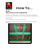
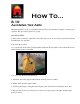
How To… 8.01 Adjusting the Tabletop Follow these steps to set up the tabletop. Once the tabletop is set up correctly, it is unlikely that it ever need to be adjusted. If the table does for some reason need an adjustment, just skip the first step. SOLUTION STEPS: 1. Line up the aluminum spine between both halves of the table. 2. Tighten the nuts and bolts that draw the two halves of the table together, but don't completely tighten them.
3. Check that the tabletops meet evenly by running your fingers across the seam on the top of the table. If they don't meet perfectly, gently tap the half that is out of alignment with a rubber mallet. 4. Tighten the tabletop nuts down completely once they are level. 3. Adjust 10 x 1/4 screws that hold the tabletop to the frame.
How To… 8.02 Adjusting the Fence The fences on the work surface should be in perfect square to act as a reference during the construction process. The vertical and horizontal fences are held in place with allen head screws. The screws holding the fences in the bottom left of the tables are fixed. The other allen screws are adjustable. SOLUTION STEPS: 1. Make sure all the allen screws are loosened so that the fences will move with pressure, but are not completely slack. 2.
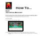
How To… 8.10 Aligning the Arm When the machine is set up or reassembled after relocation, the arm must be aligned to ensure proper operation. This procedure requires two people. SOLUTION STEPS: 1. If the arm is not already on the table, remove the stop bolt on one end of the top beam and slide the assembled arm onto the table. 2. Re-insert the stop bolt. 3. Loosen the four bolts in the top bracket that hold the arm in place while someone holds the bottom bracket firmly in place on the table. 4.
How To… 8.21 Adjusting Bracket The brackets that hold the two halves of the frame together are called the four-bolt brackets. The one at the top of the frame is located inside the beam and has four bolts welded to it. If this top bracket is not aligned and tightened down properly then the arm will not roll evenly. SOLUTION STEPS: 1. Loosen all of the four-bolt brackets slightly. 2. Tap the frame gently at the upper four bolt bracket with a rubber mallet to align the halves.
3. Check the bottom frame seam to make sure it is still even. Using a clamp in this position will help in the same way as Step #2. 4. Tighten the top four bolt bracket first, then tighten the bottom four-bolt bracket. 5. Roll the arm across the center of the table to check for smoothness. 6. Tighten the two four-bolt brackets in the middle of the frame. 7. These step may need to be repeated to get the arm to roll smoothly.
How To… 8.22 Adjusting the Arm Bearings The arm rides on two sets of bearings, one at the bottom bracket and one at the upper bracket. If the arm becomes loose or rides on the beam roughly, then these bearing sets may need to be tightened. This procedure requires two people. SOLUTION STEPS: 1. LOOSEN the four bolts in the top bracket that hold the arm in place while someone holds the bottom bracket firmly in place against the table. 2. Do not loosen the bottom bracket bolts.
3. Locate the bearings attached to the upper bracket that ride on the top of the beam. Tighten the bolt head on one side of the bearing while holding the nut on the other side of the bearing. 4. It is important that these be tightened down firmly. 5. After tightening the bearing nut on the front of the upper bracket, the nut on the rear of the upper bracket should be tightened next. 6. Do this by holding the nut closest to, and in front of the bracket, while tightening the nut at the rear of the bracket.
How To… 8.30 Tightening Bracket Bolts The bottom bracket is held to the aluminum clamp bar by two bolts. If either of these bolts are loose or slightly tweaked out of shape, the pneumatic seal won’t hold. It is important that these bolts be tight, but they are tapped directly into the aluminum so if they are over-tightened they will strip the arm out. SOLUTION STEPS: 1. Check that the bolts on the bottom bracket are tight. 2.
How To… 8.40 Tightening the PEM Nut The cylinder lever is held against the body of the cylinder with a PEM nut. This nut can be tightened by first removing the cylinder and then tightening up the nut. SOLUTION STEPS: 1. Remove the arm from the upper bracket by removing the bolts in the bracket. This can be done with the arm on the machine, but will require a second person to hold the bottom bracket firmly against the table. 2. Turn off the air and remove the airline for the cylinder with the loose lever.
3. Loosen the tension screw on the side of the cylinder bracket Bracket Slide Screws 4. Take out the two bracket slide screws on each side of the cylinder bracket, and pull the whole assembly off of the arm. 5. Tighten the PEM nut at the top of the cylinder and check the action of the lever. It should be relatively difficult to move when it is off of the arm. 7. Slide the cylinder(s) back onto the arm. 8. Replace the cylinder assembly, including the cylinder bracket, back onto the arm.
How To… 8.42 Removing Cylinder The cylinders have several rings and gaskets that help maintain pressure within the cylinder itself. Over time these seals can become worn or damaged and may need to be replaced. Refer to the parts explosion and corresponding list below for specific part identification. This procedure requires two people. SOLUTION STEPS: 1. Turn off the air and remove the airline for the cylinder to be removed/rebuilt. The line is connected to the cylinder by a push-in fitting.
Bracket Slide Screws 4. Take out the two bracket slide screws on each side of the cylinder bracket (4 total), and pull the whole assembly off of the arm.
How To… 8.50 Rebuilding Cylinder The cylinders have several rings and gaskets that help maintain pressure within the cylinder itself. Over time these seals can become worn or damaged and may need to be replaced. Refer to the parts explosion and corresponding list below for specific part identification. This procedure requires two people. SOLUTION STEPS: 1. Turn off the air and remove the airline for the cylinder to be removed/rebuilt. The line is connected to the cylinder by a push-in fitting.
Bracket Slide Screws 4. Take out the two bracket slide screws on each side of the cylinder bracket (4 total), and pull the whole assembly off of the arm. 5. With the cylinder off of the arm, remove the snap ring - (2) on the parts explosion 6. Remove the piston (1) 7. Remove the PEM nut(10) and the screw (4) in the center. 8. Remove the large washer (5) and the gasket (6) 9. Remove the piston assembly from the elbow (17), (18), (19) 10.
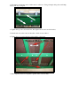
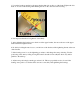
Clamp Piston Detail
AT Cylinder Rebuild Kit Drawing 1 of 2 - Clamp Cylinder Detail Item # Part # Part Description Qty 4 F10377 Screw, Machine 10-32 x 7/8 PPMS 1 5 M08615 AT Stainless Steel Washer 1 6 N00051 AT Reinforced Neoprene Rubber Gasket 1 10 F32012 AT Pem Stand-Off 1 11 F10000 # 10 SAE Flat Washer - 90126A11 1 17 H00352 Buna-N O-Ring - 003 1 19 H00600 Buna-N O-Ring - 006 1 Drawing 2 of 2 - Cylinder Piston Detail Item # Part # Part Description Qty 8 H32200 Buna-N O-Ring - 322 1 Not
How To… 8.90 Adjusting the Regulator The air for the machine is taken in and controlled through the regulator at the top of the machine. If the air pressure seems low, it can be checked and adjusted at the regulator. SOLUTION STEPS: 1. Visually check that the regulator gauge reads between 80 and 85 PSI. 2. If it does not, then pull the regulator knob to release it from its locked position. 3. Turn the knob while watching the gauge until it reads the appropriate pressure. 4.