Castle System Drill 30 Express Operator’s Manual Castle, Inc.
Table of Contents Safety Notification…………………... Page 1 Machine Parts Inventory..…..………. Page 2 Machine Requirements……………… Page 2 Setting Up…………………………… Page 3-5 Operating Instructions……………… Page 6-7 Machine Adjustments………………. Page 8-11 Definition and Description of Parts… Page 12-14 Maintenance ……………………….. Page 15 Troubleshooting…………………….
DO NOT OPERATE THIS MACHINE UNTIL YOU HAVE READ THIS MANUAL COMPLETELY. Safety Notification WARNING: This machine was carefully prepared for shipment at our factory. Upon receipt of this machine, inspect for shipping damage. The Castle 30 Express System Drill was designed with operator safety as a priority. Report any damage immediately to the freight company, your Castle dealer and to Castle, Inc. DO NOT attempt to operate this machine if you observe any physical damage. Contact Castle, Inc.
Inventory With your Castle machine, you should have received the following: Warranty Card (Please fill out & mail to Castle, Inc. to activate your warranty) 30 Express Operator’s Manual One bottle of Line Boring Oil Left and Right Side Stop Assemblies 4” Dust Collection Port Tube Magnetic Sheet for Dust Collection Machine Requirements Electricity: 220V, Single Phase Air Supply: 80 PSI minimum, 150 PSI maximum Never use an extension cord to power this machine.
Setting Up Your 30 Express Your Castle 30 Express system drill was set up at the factory and tested for proper operation. It is normal to find a small amount of sawdust residue in the machine as a result of this process. Begin set up on your 30 Express by removing the Phillips head screws from each corner of the machine that attach the machine to the pallet. Position and secure your machine in a chosen location.
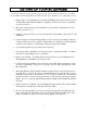
Now that the tape is calibrated you are ready to drill your first test panel. The Front Auto-Fence is factory set to 37mm from the center of the Drill Bits to the front edge of the board. Insert your first test panel under the Clamp Beam with the front edge of the panel facing in, toward the Front Auto-Fence and the bottom edge of the panel toward the Right Stop. If the Front Fence is up tap the Foot Pedal to toggle it down.
Pull the Black Fence Knob toward you, dropping the Middle Fence into place. Again, slide the panel to the right until it is pressed against the Right Stop. Keep Your Fingers Away From the Clamping Beam. Step on the Foot Pedal again and wait for the machine to complete its drilling cycle. Release the Foot Pedal. You have just drilled the rear line of holes for a 12” panel OR the middle row of a deeper panel.
Operating Instructions Always use eye protection when operating power equipment. Your 30 Express was designed for boring both European type 32mm panels and American Face Frame type cabinet construction. Since the distance between the Bits is only critical for European style panels, your drill is using 32mm increments center to center between drill bits and will drill 5mm diameter holes. This hole placement should not effect American style panels.
Drilling Panels Longer than 42” in length If you are drilling a 96” x 12” panel for full height shelving units, use the same procedures as you did for the 42” x 12” panel in the previous application. Drill the first row of holes using the Right Stop. Whenever the Toggle Switch is flipped, the first cycle will drill, then the second cycle will index.
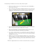
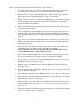
Machine Adjustments Removing Bits for Standard Base Cabinet Panel Drilling If you do not want holes to run off the top of the panel when drilling standard base cabinet panel, you can remove the additional bits or Index earlier in the panel. To remove bits, pull the hand return plunger on the right side of the black head cover and swing the cover down. If the Plunger seems resistant to being pulled out, push against the cover with your hip a bit to relieve the pressure on the pin.
Remove the Bits by turning the Collet counter clockwise. They require 1 ½ turns to remove. The removed bits should be placed in their respective location holes in the Top Rear Hole Pattern on the Yellow Clamp frame.
Adjusting for Panel Width The Auto Fence is set for 37mm from the center of the drilled 5mm hole to the front edge of the panel. This is designed to accept European Cabinet Hardware. (i.e., hinge plates and drawer slides.) The Middle Fence behind the Front Auto-Fence can be adjusted forward or to the rear, but only at 32mm increments. The Fixed Rear Stop has additional slotted adjustments and must be set separately. Each adjustment hole on the side is in 32mm increments from the First Fence.
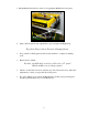
Hole Depth The depth of the holes is adjustable on the right side of the machine. Using a 7/16” wrench, loosen the Hex Head Bolt that holds the lower end of the yellow Drill Depth Bar and insert a screwdriver into the slot. Using the screwdriver, move the bar up or down approximately 1/8” at a time. This will adjust the depth of drilling. Up movement on the bar increases the depth of holes while Down decreases the depth of the holes.
Description of Parts Air Pressure Regulators The Regulators are mounted on the back side of the Control Box on the inside of the machine. Bit Cover The Bit Cover is the surface you place your work on when you are drilling. It also opens and swings down using a Hand Return Pluger on the side. When the Bit Cover is open you have access to the bits and Drilling Head. NOTE: If the Bit Cover is open the machine will NOT start.
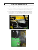
Drop Gauge, Manual The Middle Fence is operated by a manual Drop Gauge Lever. This Lever drops the fence into place for drilling the second row of holes on a standard Upper, or the middle row for a deeper panel. Dust Port Tube The Dust Port Tube is mounted inside the green Dust Chute. The Dust Port Tube is used to hook up Dust Collection to the machine. If you are using Dust Collection, flip the Tube and remount it so that it partially sticks out of the hole.
Indexing Toggle Switch The Index Toggle is located on the top of the Clamp Frame. When the Toggle is in the center position the Index Pins are inactive. When the Toggle is in the left or right position, with exception to the first cycle after switching, the machine will not drill unless the left or right (depending if the switch is in the left or right position) Index Pin is seated in a previously drilled hole.
Maintenance Oil the Drive System Regularly There are two large Oil Wicks inside the Head that hold the oil and dispense it to its proper location. If your machine begins to drip oil from the Locomotion Drive System while you are using it, then it has been over oiled. Just wipe up the excess oil, it will not hurt your machine or its operation and you should back off on the number of drops of oil added each 30 hours of operation.
Troubleshooting Do not attempt to work on the gray electrical box unless you are instructed by a qualified Castle representative and you are a licensed electrician. This will void your warranty. Machine Does Not Start Check to see that the machine has air connected to it and that the air is in the ON position at your wall outlet. Check to see that you are connected to the proper power supply and that you have 220V single phase electric coming directly into the machine on a minimum 15 amp circuit.
Remember, just a slight turn of the screw makes a lot of adjustment. 1/2 turn and THEN test. Drill a row of holes, holding the material so the last hole is less than 32mm away from the end of the board. Open the head cover and place the drilled board over the drill bits and one of the index pins. The bits and pin should fit. Repeat on other side. If the bits don’t line up with the index cylinder perfectly, use a 7/16” open end wrench to loosen both nuts holding the index cylinder.
Warranty Information Castle, Inc. uses only the highest quality materials available for the construction of our machines. Your 30 Express System Drill is warranted for one full year from the date of purchase against workmanship or material defects under normal use and service. We are not responsible for negligence, misuse or accidents. We suggest any and all machine maintenance or repair be discussed with an authorized Castle Representative prior to any disassembly.