
User's Guide

© 2013 Castle Creations, Inc. P/N: 095-0176-00 Revisi on Date - 03/2013 PAGE 2 of 6
NOTE TO USERS WITH A FUTABA TRANSMITTER: You must reverse the throttle channel signal on your transmitter. Please
refer to your Futaba instructions.
5. Reversing rotation (if necessary)
You may wish to bench test the motor and speed control to determine the rotation of the motor. To change the rotation of
the motor, swap ANY two motor wire connections, or use the Castle Link USB interface to change the rotation direction.
6. Mounting the ESC
Edge ESCs have mounting tabs for your convenience. We recommend using Velcro or double sided tape to attach the Edge
LITE ESCs to the airframe.
Never place undue strain on the ESC by using zip ties on the wires within 1 inch of the controller.
Never use zip ties on the body of an Edge LITE controller.
7. Initialization sequence
1. Ensure that the Edge is connected to the throttle channel on your receiver.
2. Turn your transmitter ON and set the throttle stick to mid-throttle.
3. Connect the motor battery to the speed controller. The speed controller will remain disarmed and will not operate the
motor until it receives the 0% throttle signal.
When you are ready to fly, move the throttle stick to the lowest position on your transmitter.
The Edge will beep the motor to indicate that it is armed.
Always power your radio transmitter before powering up the receiver and/or the ESC. Some receivers failsafe features,
those that are not bound to a transmitter on receiver power up, or those that have a “power-up” output signal that is
dierent from fail safe settings or the stick positions on the TX may cause the arming sequence to occur and command the
ESC to drive the motor.
Using channels other than the radio TX manufacturer’s recommended throttle channel may lead to unwanted or dangerous
results. Use non-throttle channels to control the ESC at your own risk.
Always perform a range check at full, half, and zero throttle before flying any new speed controller! For helicopters, range
check with the blades o the helicopter at full, half, and zero throttle.
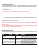
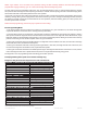
EDGE BEEP CODES/ LED PATTERNS
Edge ESCs are programmed to sound a number of tunes and codes using the motor as well as flashing LED patterns to alert
the user to certain conditions regarding the power system. The following chart describes these codes, “•” represents a short
beep and “
-
” represents a long beep.
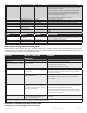
TONE EDGE LED MEANING DESCRIPTION
“Castle Power” tune with
beeps corresponding to
number of cells
Blinks out cell count with
RED LED
Power up notice ESC plays Castle signature tone and beeps out the number of
cells attached to controller. Note: when Auto-LiPo detection is
disabled by the user, ESC will not beep the number of cells. ESC w
ill not run motor until it receives an arming signal from the radio
via the throttle lead.
Arming tune none ESC ready to run motor ESC plays the Castle arming tune once it receives a signal from
the receiver. Controller is ready to run the motor at this point.
• RED LED matches tone Powered ESC notice ESC beeps motor every 10 seconds to remind user that power is
connected to the ESC. This notice may be disabled in Castle Link.
•
-
RED LED matches tones Low Voltage Cuto Main battery voltage dropped below the cuto value. The default
is Auto-LiPo which sets the cuto value based on the detected
cell count. Other settings may be entered in Castle Link.
•
-
• RED LED matches tones Over Temperature ESC reached an overtemp condition. Occurs when operated under
too high a load or operated without proper cooling airflow.