
User Manual

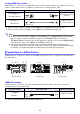

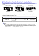

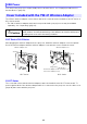

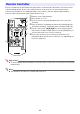
Table Of Contents
- Contents
- Safety Precautions
- Operating Precautions
- Getting Ready
- Unpacking
- Operation Flow to Projection
- General Guide
- Key and Indicator Panel
- Back Terminals
- Placing the Projector on a Desk or on the Floor
- Connecting with Another Device
- Connecting a Computer
- Connecting to a Video Device
- Outputting Audio from the Projector to Another Device
- Connecting a Microphone (XJ-UT Series, XJ-F21XN, XJ-F211WN, XJ-S400UN, XJ-S400WN)
- Connecting to a Network with a LAN Cable (Network Models Only)
- Connecting a Wireless Adapter (Network Models Only)
- LOGO Terminal (Firmware Updates, User Logo Transfers)
- Connecting a Scientific Calculator (Network Models Only)
- SERIAL Terminal (Projector Control Using Commands)
- USB Power
- Cover Included with the YW-41 Wireless Adapter
- Attaching and Removing the Cable Cover (XJ-UT Series)
- Remote Controller
- Operating the Projector
- Turning the Projector On or Off
- Selecting an Input Source (INPUT)
- Using Auto Projection Off
- Basic Image and Audio Operations During Projection
- Flipping the Projected Image Horizontally (Mirror Mode)
- Light Control
- Digital Screen Shift
- Projecting a Template
- Test Pattern Projection
- Control Panel Lock
- Configuring Remote Control ID and Projector ID Settings
- Using the Countdown Timer (TIMER)
- Using the Presentation Timer (TIMER)
- Using the Setup Menu (MENU)
- Using a Password
- Cleaning the Projector
- Troubleshooting
- Appendix
- Supplying USB Power to Another Device
- Mounting the Projector on a Wall (XJ-UT Series)
- Hanging the Projector from a Ceiling
- Using the MONITOR OUT Terminal (XJ-UT Series, XJ-S400UN, XJ-S400WN)
- Projection Distance and Screen Size
- Aspect Ratio Setting and Projection Image
- Supported Signals
- Projector RS-232C Control
- Specifications

33
Component Video Connection
Video device component video output terminals are grouped as a set of three: Y, Cb, Cr or Y, Pb, Pr.
Connect the component video cable so the colors of its three plugs match the colors of the terminals
(green for Y, blue for Cb or Pb, red for Cr or Pr). If you want to output the audio of the video device
through the projector’s speaker, you also will need to connect an audio cable.
Composite Video Connection
Video device composite video output terminals are grouped as a set of three: video (yellow) and audio
(white and red). Use a video and audio RCA cable to connect to the like-colored terminals of the
projector.
Note
The relationship between the image output terminal and audio output terminal can be
changed as required. Note that the combinations shown in the table are initial default settings.
For details, see “Relationship Between Image Input and Audio Input” (page 45).
Projector Terminal Connection Cable Video Device Terminal
COMPUTER IN 1*
2
or
COMPUTER IN 2
Component Video Out
terminals
AUDIO IN 1*
3
or
AUDIO IN 2
Audio Out terminals
*2 An XJ-F Series model, XJ-S400U, or XJ-S400W has a COMPUTER IN terminal only.
*3 An XJ-F Series model, XJ-S400U, or XJ-S400W has an AUDIO IN terminal only.
Projector Terminal Connection Cable Video Device Terminal
VIDEO,
AUDIO IN R/L
Composite Video Out/
Audio Out terminals
Component video cable
15-pin Mini D-Sub
Audio cable
Stereo mini jack
RCA audio video cable
RCA jacks