PA-2400 Software Manual (Version 1.00 ) March 1998 Casio Computer Co., Ltd. Copyright ©1998. All rights reserved.
Table of Contents Chapter 1. 1.1 1.2 1.3 1.3.1 1.3.2 1.3.3 1.3.4 Chapter 2. 2.1 Chapter 3. 3.1 3.2 Chapter 4. 4.1 4.2 4.3 4.4 Chapter Chapter Chapter Chapter Chapter Chapter 4.5 4.6 4.7 4.8 5. 6. 6.1 6.2 7. 8. 9. 9.1 9.2 10. 10.
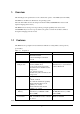
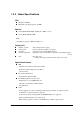
1. Overview This manual gives the specifications of the software that operates on the H/PC (Casio PA-2400). The H/PC uses the Windows CE US Ver 2.0 operating system. The Casio PA-2400 is the next model up from the PA-2100 (CASSIOPEIA Pen Version with Japanese-language OS Ver1.01) . This H/PC has been developed for export. It has pen input capability and is based on the CASSIOPEIA Key Version for export, which is the generic consumer model that is similar to the Japanese-language Ver1.01 model. 1.
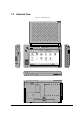
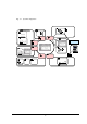
1.2 External View ADP LIGHT CASSIOPEIA POWER 3P Fig. 1.
1.3 Specifications 1.3.1 Hardware Size Weight Battery 179 mm (W) x 107 mm (D) x 21 mm (H) Approx. 370 g Lithium-ion battery pack (main battery) Alkaline batteries (LR6 x 2) can also be used as substitution. CR2032 x 1 + IVR2430 x 1 (sub-battery) Operating hours Lithium-ion battery pack Approx. 10 hours (adequate for 90 Pocket Word strokes/minute) or Approx. 15 hours in “10:1” mode Alkaline batteries LR6 x 2 Approx. 10 hours (adequate for 90 Pocket Word strokes/minute) or Approx.
Fig. 1.2 System Configuration # $ +! & !78 1 - % %9# - $ +! & !78 % $ . / 0 / / $ # & ) $ * " !" '" (% &) + ) .
1.3.3 Basic Specifications CPU Hitachi 32-bit RISC Maximum operating frequency: 80 MHz Memory System ROM: Mask ROM: 16 MB (OS: 8 MB x 2) (note) System RAM: DRAM: 8 MB Note: PA-2500 incorporates 8 MB (OS: 4 MB x 2) Display Unit Number of pixels Touch panel Gradation Contrast adjustment Font : 480 x 240 (0.
1.3.4 Option Recommended options for PA-2400 can be found on the Microsoft Web pages or by information available from Casio. The user assumes all responsibility for the use of optional products with the PA-2400 not recommended by Casio nor by Microsoft.
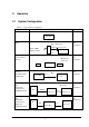
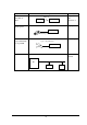
2. Operation 2.1 System Configuration Table 2.
Operation Mode PA-2400 and PA-2400 via IrDA System Configuration IrDA 1.
3. Bootup Procedure 3.1 Bootup Method The PA-2400 (Windows CE, Ver 2.0) will boot up in one of the following three ways: Cold-bootup Start If no data is stored in Object Store (e.g. if the sub-battery is being replaced) and after the diagnosis program has been executed, a Power-ON start from "Power-On factor" will initialize Object Store, boot the OS, make user setups, and execute Welcome Wizard.
Battery is installed. File area is cleared. Cold-bootup (Battery is not installed) Work area is cleared. Warm-bootup (Reset SW) Device is ready for startup. Fig. 3.1 Bootup Process 3.2 Bootup with Special Key Sequence To aid maintenance or application development the following functions can be initiated depending on simultaneous key and switch operation. In case the bootup is done by this method, the RESET SW should be pressed last. Table 3.
4. Power Control 4.1 Power-ON Factors Power-on factors include: The power is turned on by pressing the POWER SW. The power is automatically turned on at the specified time by the alarm function. The power is automatically turned on if the CD signal is detected by the PA-2400 connected to PC via the RS-232C cable. The power is automatically turned on when the PA-2400 is mounted on I/O Box. (This function is not supported for the PA-2500.
Note: The screen on the PA-2400 changes to reverse if the power is turned off (only in the first case above). This is a unique feature for turning off the power safely, not to loose data. If the power key is turned off when, for example, a card is being accessed or other high-priority process is in progress, the screen temporarily changes to reverse. The actual power-off process will take place after the system enters the idle state.
Fig. 4.2 ABO setup screen 4.5 Low Battery Level Monitoring On the PA-2400 there are three low battery levels. Table 4.1 Battery voltage monitoring levels Level Contents VDET1 Low main battery voltage alarm VDET2 VDET3 4.6 Power off due to low main battery voltage Low sub-battery voltage alarm Operation Indicates low main battery voltage alarm Turns off the power.
Fig. 4.4 Low sub-battery voltage alarm screen 4.7 Remaining Battery Voltage Indication The remaining battery voltage can be displayed if the Power Management icon or Battery icon is touched on the Control Panel. Fig. 4.5 Battery property display screen Note: The "LOW" indication also appears if a VDET1 event occurs, even if it occurs when the backlight is on. If the voltage is "Low" or "Very Low" the backlight can not be restored to ON.
4.8 Recharging and Power Supply The main battery (lithium-ion battery pack) can be recharged in three ways as follows: Replace with a fully charged lithium-ion battery pack. Remove the battery pack and charge it using the battery charger (PA-2040DCHG-E). Set the battery pack in the PA-2400, then mount the PA-2400 on the I/O Box to charge the battery pack.. Retain the battery pack in place of the PA-2400, then connect the AC adaptor (AD-C50200-S) to the PA-2400.
5.
6. Input Method 6.1 Key Input The names and functions of Ver 1.01 keys have been modified, as follows: Table 6.1 Comparison Ver1.01 LIGHT (Backlight ON/OFF) CALIB (Calibration Start) Ver2.0 SIP (Software Input Panel ON) LIGHT (Backlight ON/OFF) SIP+LIGHT (Calibration Start) The SIP key toggles between ON and OFF. 6.2 Alphanumeric Input Pad This software-type input pad can be initiated if the icon in the task bar is touched. Alphanumeric input pad Fig. 6.
7. Fonts Only true type fonts can be used. It is possible to add more font types to the pre-installed fonts. To do this, use Mobile Devices to download the font from the Windows Fonts directory on the PC to the PA-2400. This operation converts the original font via the font filter to a format that can be used on the PA-2400. After download, switch to the desired font on the PA-2400. Table 7.
8. Registry The following list shows the registry values that have special meanings on the PA-2400. Default of SIP key [HKEY_LOCAL_MACHINE Software Apps SIPManager] "SIPExeName"="smARTkbd.
9. Application Development Environment 9.1 Overview User applications may be developed under the following development environment. Table 9.1 Application development environment Development platform Microsoft Windows NT4.0 (English version) Development language Microsoft Visual C++ Ver5.0 + VC for Windows CE (US Ver2.0 SDK/DDK) Microsoft Visual Basic Ver5.0 + VB for Windows CE (US Ver2.0 SDK/DDK) Microsoft Visual J++ Ver1.1 + VJ for Windows CE (US Ver2.0 SDK/DDK) 9.
Flow-chart of Development Procedure Edit source code Edit resource. Compile/link X86 Debug Debug emulation Compile/link SH Debug Transfer debug module Remote tool/ Execute debug Remote debug Compile/link SH Release Transfer release module Execute PC side PA-2400 side Fig. 9.1 Software development procedure For more information refer to the Microsoft Visual C++ Ver5.0 and other reference manuals published separately for Windows CE.
10. Appendix 10.1 Differences from PA-2500 (US Ver.2.0) Keyboard The PA-2400 is not equipped with a hardware keyboard. Characters are input from the software input panel. Calibration Holding down the SIP and LIGHT keys simultaneously initiates the calibration. (To quit this operation, touch anywhere on the screen.) Power supply terminal The power supply can be started by simply mounting this PA-2400 on the I/O Box.