(without price) Handheld Personal Computer PA-2500U(PX-675) FEB.
CONTENTS HARDWARE SPECIFICATIONS -------------------------------------------------------------- 1 General Specifications ------------------------------------------------------------------- 1 Electrical Specifications----------------------------------------------------------------- 2 ACCESSORIES ------------------------------------------------------------------------------------ 3 OPTIONS --------------------------------------------------------------------------------------------- 3 SYSTEM CONFIGURATION ----
POWER SUPPLY CIRCUIT ------------------------------------------------------------------Primary Circuit---------------------------------------------------------------------------5 V Circuit ---------------------------------------------------------------------------------3 V Circuit ---------------------------------------------------------------------------------PCMCIA Circuit --------------------------------------------------------------------------LCD power Circuit ------------------------------------------
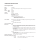
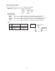
HARDWARE SPECIFICATIONS General Specifications Model: PA-2500U Display: 640 × 240 dots/0.24 dot pitch, FSTN LCD, 4 grayscale monochrome CPU: Memory RAM: ROM: SH3 8M bytes 8M bytes Speaker: Sound Interfaces: RS-232C: 115.2K BPS Data communication jack PC card slot CompactFlash card slot Infrared port (IrDA compatible protocol) Communication distance: 10 to 70 cm Maximum Speed: 115.
Electrical Specifications Current Consumption (V-in: 2.6 V ± 0.1 V, LCD Contrast VR: MID.): Main Battery: Diagnostics Program with alkaline batteries 80 MHz: 650 mA or under Sleep: 50 mA or under Standby: 1.4 mA or under Back-up Battery: OFF: 450 µA Voltage Detectors: VDET1: 2.0 V ± 1% V or under (Low battery message detector for alkaline batteries) VDET2: 1.6 V ± 1% V or under (Foced power off detector for alkaline batteries) VDET1R: 3.
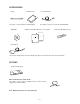
ACCESSORIES • Stylus • Dummy Card The stylus is inserted into the CASSIOPEIA. • CD-ROM • RS-232C Cable The dummy card is inserted in the CASSIOPEIA. • Manuals (Hardware Manual, User’s Guide) • Rechargeable Battery Pack • AC Adapter *The actual configuration of the AC adapter may differ from that shown in the above illustration. OPTIONS • Cradle PA-2010 IFS Data Communication Cable SB-62 This cable is used to connect a digital camera or other external equipment to the PA-2500U.
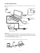
SYSTEM CONFIGURATION Note that CASSIOPEIA will not operate under AC adapter power alone if its main batteries are not loaded. AC adapter CASIO Digital Camera Data communication cable (SB-62) Infrared port CASSIOPEIA Desktop Computer Printer CompactFlash Card PC Card CD-ROM RS-232C Cable Printer Converter Desktop Computer Important If you have a notebook PC with IrDA capabilities or a built-in modem, its COM port may not be set up for use as a standard serial interface.
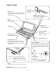
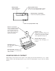
GENERAL GUIDE • Touch screen Displays text data and operational indicators, as well as icons that can be operated using the stylus. • Infrared port For infrared communication • Data communication jack For connection of a digital camera or other external equipment. • Speaker Outputs alarm tones and other sounds. • Microphone For voice and other sound recording. • Keyboard • Card eject button (PC card) Press to eject the card from the card slot.
• Battery holder Holds main batteries (AA-size alkaline). • Battery holder release Slide to release the battery holder to remove it, or to secure the battery holder in place. • Backup battery compartment Holds the backup battery (CR2032). • Card cover (CompactFlash card) • Indicator clear button Clears a warning indicator (red) and alarm operation. Pressing this button also turns on power. Power can be turned off only by pressing the power button.
DESKTOP COMPUTER SYSTEM CONFIGURATION The computer configuration described below is required to support the installer and the software applications contained on the Microsoft CD-ROM supplied with the CASSIOPEIA. • Microsoft Windows NT Workstation 4.0 or Windows 95 (U.S. version) • Desktop computer with a 486/33DX or higher processor (Pentium P90 recommended) • 12 MB of memory for Windows NT Workstation 4.
Important • Should the display lock up or go blank at this time, first perform the full reset (page 12). If this does not correct the problem, remove the main batteries from the CASSIOPEIA and then remove the back-up battery. Wait for about five minutes, and then perform this procedure again, starting from step 1. Be sure that the positive (+) and negative (–) poles of the batteries are facing correctly when you reload them into the CASSIOPEIA.
REPLACING BATTERIES The CASSIOPEIA has a dual power supply that consists of main batteries and a backup battery. Be sure to load the main batteries and a back-up battery before using the CASSIOPEIA for the first time after purchasing it. Also, replace batteries as soon as possible after they start to get weak. Important! • Never remove both the main batteries and the backup battery from the CASSIOPEIA at the same time. If you do, data stored in memory can be corrupted or lost entirely.
5. Reattach the battery holder to the CASSIOPEIA. • The battery holder will emit a click and the battery holder release will automatically lock when the battery holder is securely in place. To replace the backup battery 1. Make sure the CASSIOPEIA is turned off. • If the CASSIOPEIA is on, press the power switch to turn it off. 2. Close the CASSIOPEIA and turn it over. 3. While pressing the release A with the stylus, slide the backup battery cover from the CASSIOPEIA. 4. Remove the old battery. 5.
RESET You should reset the CASSIOPEIA whenever it stops working or whenever some other operational problem has caused it to malfunction. To reset the CASSIOPEIA 1. Press the RESET button with the stylus. • This automatically turns off CASSIOPEIA power. 2. Press the power switch to turn on power and start the reset process. • What happens next depends on memory status. Case A: Memory Contents Not Corrupted In this case, the display changes in the sequence shown below.
FULL RESET Perform the full reset when you want to clear all memory contents and settings because memory contents are corrupted, because you have forgotten the security code, or for any other reason. Important The following procedure deletes all data in memory. Be sure to save any important data contents you may need later to a computer disk or other medium. Always keep separate back-up copies of important data. To perform a full reset 1.
CONNECTING TO A DESKTOP COMPUTER Use the following procedure to connect the CASSIOPEIA to a desktop computer. Note that exchanging data with a desktop computer requires Microsoft Windows CE Services, which is on the Microsoft CD-ROM that is included with the CASSIOPEIA. Requirements RS-232C cable (supplied with CASSIOPEIA) To connect to a desktop computer 1. Open the RS-232C connector cover on the side of the CASSIOPEIA. 2. Slide the cover into the CASSIOPEIA case as shown below. 3.
REPLACING THE PC CARD The CASSIOPEIA comes equipped with a PC card slot that supports memory, modem and other PC cards*. * Use only PC cards that are compatible with the CASSIOPEIA. Important • Be sure to keep the dummy card that comes with the CASSIOPEIA inserted in the card slot whenever you are not using a PC card. • Be sure to save any unsaved input or edited data before replacing the PC card. • Never remove the PC card from the CASSIOPEIA while a PC card operation is in progress.
REPLACING THE COMPACTFLASH CARD The CASSIOPEIA comes equipped with a card slot that supports CompactFlash cards. Important • If the card stops part way into the slot, do not try to force it. Doing so can damage the card or the CASSIOPEIA. Remove the card, make sure it is oriented correctly, and then try inserting it again. • Be sure to save any unsaved input or edited data before replacing the CompactFlash card. To replace the CompactFlash card 1. Make sure that CASSIOPEIA power is turned off. 2.
CONNECTING TO EXTERNAL EQUIPMENT You can connect external equipment to the data communication connector. You can also use special software to set up the CASSIOPEIA to exchange image data with a CASIO digital camera. See the documentation that comes with the software for details. Requirements Optional data communication cable (SB-62) To connect external equipment 1. Make sure the external equipment and CASSIOPEIA are both turned off. 2.
MEMORY BACKUP / RESTORE Make the backup copy by Windows CE Services to your PC before repairing PA-2500U, and restore the data from PC to user’s PA-2500U after repairing. For the details of Backup/Restore, refer to the operation manual of Windows CE Services. Notes: 1* Backup program of Windows CE Services back up only files and databases. Setup data including Owner, World Clock and so on, can not be backed up to PC. 2* Use AC adaptor when making backup copy and restoring. Backup 1.
6. Click “Full: back up all data” and “Back Up Now”. 7. Confirm the file name of bakup copy and then click “OK”. Backup starts.
Restore Execute Restore after repairing. 1. Turn on the user’s PA-2500U and then Welcome wizard appears. 2. Execute touch panel calibration and then skip other setups after calibration. 3. Connect repaired PA-2500U to your PC with RS-232C cable. 4. Start Windows CE Services on your PC. 5. Click “Restore” and confirm the file name backed up. Then click “OK”. 6. Click “Restore”.
7. Restoring starts. 8. Click “OK”.
BLOCK DIAGRAM 10 M 32.768 K PLL X4 80 MHz CPU SH-7093 (IC1) RAM 8 Mbyte HM51W16165 (RAM5~RAM8) CompactFlash Card ROM 8Mbyte Memory Slot (U301~U305) PCMCIA Audio Amp. MC34119 (IC9) Card 3.68M SP LCD unit Mini Jack LCD IrDA IrDA Transceiver Gate Array CIM-10S (IC4) RS232C Connector RS232C Transceiver MAX3241 (IC5) MB87A915 (IC3) EL EL Driver HV803 (IC801) Touch Panel Indicator (Red) LED +3.
DEVICE FEATURES Device Features CPU SH-7093 (IC1) Hitachi 32 bit RISC CPU. Sleep/Standby Power Mode. TLB supports 1K/4K bytes page,128 entries. 8K bytes Cash. Interrupt Controller. User Break Controller. Bus State Controller. Watch Dog Timer. CASIO proprietary RTC. 2K bytes Mask ROM. ON Controller. 1 ch Serial I/F. 1 ch Serial I/F with 16 bytes FIFO. 1 channel Reload Timer. 2 channel Free Run Timer.
Device Touch Panel A/D Features 10 bit analog to digital converter in System LSI. Audio D/A 10 bit digital to analog converter in System LSI. 8/11.025/22.05 kHz sampling. Audio A/D 10 bit analog to digital converter in System LSI. 8/11.025/22.05 kHz sampling. Speaker PCMCIA 20 mm dynamic type. One slot for PCMCIA Type I/II card. Compliance with PCMCIA ver.2.1. IrDA / RS232C (alternative) Serial I/F with 16 byte FIFO in CPU. 115.2 kbaud. IrDA 0 - 1 m. 9-pin RS232C ±12 V I/F.
LSI/IC DATA SH-7093 (CPU / IC1) No.
No.
No. 119 120 121 122 123 124 125 126 127 128 129 130 131 132 133 134 135 136 137 138 139 140 141 142 143 144 Pin Name CASHHB / CAS2HB CASHLB / CAS2LB Vss Vcc WE1B WE0B CASLHB CASLLB / OEB Vss Vcc RASB / CEB MD5 / RAS2B HSTBYB WAITB Vss RTCCLK Vcc(RTC) XTAL2 EXTAL2 Vss(RTC) Vcc D31 D30 D29 D28 Vss Io/Out Function O D31-D24 / D15-D8 select signal O D23-D16 / D7-D0 select signal GND +3.3V source O D15-D8 select signal O D7-D0 select signal O D15-D8 select signal O D7-D0 select / memory select signal GND +3.
MB87A915 (Gate Array/IC3) No.
No.
No.
No.
N o .
MC34119 (IC9) CD FC2 FC1 Vin 1 2 3 4 8 7 6 5 VO2 Gnd VCC VO1 (Top View) MAX3241CAI (IC5) VCC=3 V to 5.5 V 28 C1+ C2+ 1 + MAX3241 26 VCC R1IN 4 25 GND R2IN 5 24 C1- R3IN 6 23 EN R4IN 7 22 SHON R5IN 8 21 R1OUTB T1OUT 9 20 R2OUTB T2OUT 10 19 R1OUT T3OUT 11 18 R2OUT T3IN 12 17 R3OUT T2IN 13 16 R4OUT T1IN 14 15 R5OUT 28 24 27 V+ C2– 2 V– 3 C1 + 0.
UPD42S16160LG5B A0 to A11 I/O 1 to I/O 16 RAS UCAS LCAS WE OE VCC GND NC : Address Inputs : Data Inputs/Outputs : Row Address Strobe : Column Address Strobe (upper) : Column Address Strobe (lower) : Write enable : Output enable : Power Supply : Ground : No Connection RN5VD18CA (IC113) 5 1 OUT VDD GND NC CD 4 2 3 : Output (H=Detected) : Voltage source : Ground : No connection : Connect to capacitor for delay XC61A Series (IC100 ~ IC103,IC107,IC109,IC110,IC112) VIN VOUT 1 VOUT 2 VIN Vref 3 VSS
MAX608 (IC105,IC106) DIP/SO EXT 1 8 CS OUT 2 7 GND FB 3 6 AGND SHDN 4 5 REF (Top View) EMI FILTER ARRAY UPD23C32000LGY — 34 —
POWER SUPPLY CIRCUIT The power supply circuit consists of 5 blocks which are Primary circuit, 5 V circuit, 3 V circuit , PCMCIA power circuit and LCD power circuit as follows; PCMCIA power circuit PCMCIA 5V circuit 5 V system Fuse LCD power circuit Primary circuit Alkaline LCD 3 V system 3V circuit Li-ion AC Adapter To Detector (VSUB) Lithium Primary Circuit The voltages from both batteries, alkaline and Li-ion, apply to V5 and V3 circuits through the fuse when the batteries is loaded.
5 V Circuit DC/DC converter MAX608ESA (IC105) generates +5.11 V and it makes up 5 V system. VIO : BATDTCT: P5V : +5 V source for 3-pin jack and LCD power block. It distinguishes alkaline and Li-ion to change the load according to the battery. When alkaline is used, it is H. When Li-ion, it is L. Controls ON/OFF of DC-DC converter (IC105). From pin 166 of MB87A915.
3 V Circuit DC/DC converter MAX608ESA (IC106) generates +3.77 V and it makes up 3 V system. V3MAIN : V3SYS : V3RAM : V3ROM : ONSTATUSB : V3IRDA : PIRB : VSUB : V3AUD : PDMMYM : The reference voltage for the detector. +3.4 V source for IC1,IC3,IC5. +3.4 V source for DRAM (RAM5 ~ RAM8). +3.4 V source for ROM (U301,U302). Controls ON/OFF of V3ROM. From pin 99 of CPU. +3.4 V source for IrDA Transceiver CIM-10S (IC4). Controls ON/OFF of V3IRDA. From pin 75 of MB87A915 (IC3). +2.
PCMCIA Circuit DC/DC converter MAX1651 (IC111) generates 3.4 V VEL : PEL : VPC : PSEL5 : VCRDIF : PCRD : VCARD : PCRD2 : P5DCHG : ONSTATUSB : P5V : 5.11 V source for LCD unit. Controls ON/OFF of VEL. From pin 160 of MB87A915 (IC3). 3.4 V or 5.11 V source for detecting PCMCIA power. Power supply select signal for PCMCIA (H=5 V, L=3 V). 3.4 V or 5.11 V source for MB87A915 (IC3). Controls ON/OFF of VCRDIF, From pin 164 of MB87A915 (IC3). 3.4 V or 5.11 V source for PCMCIA connector. Controls ON/OFF of VCARD.
LCD power Circuit DC/DC converter RN5VH3 (IC201) generates LCD power and it makes up LCD power system for LCD. VDD : VAMP : PLCD : VLCD+: VTH : EVOL 0-3 : P25ON : VLCD- : ONSTATUSB : +3.7 V source for LCD unit. +7.0 V source for LCD unit. Controls ON/OFF of VAMP. From pin 159 of MB87A915 (IC3). +15.5 V source for LCD unit. LCD power source for LCD unit. LCD status. Controls ON/OFF of LCD power. From pin 167 of MB87A915 (IC3). -10.0 V source for LCD unit. Controls ON/OFF of LCD power.
Voltage Line IC1 SH-7093 CPU IC3 BGA288 GATE ARRAY U301/U302 32M-MASK ROM CN5 3P Jack Connector PCMCIA Connector RS-232C RAM5~8 ECSTOJY106R D-RAM IC5 MAX3241 RS232C V3AUD V3RAM V3SYS V3ROM V3IRDA VCRDIF VIO VCARD VLCD+ VLCD– VDD VEL VTH Connector CF — 40 — Connector LCD unit IC9 MC34119 AudioIC IC4 CIM-10S IRIC
DETECTOR CIRCUIT The detector circuit consistes of 7 blocks as follows; 1 : VDETECTOR1 (Alkaline and Li-ion) 2 : VDETECTOR2 (Alkaline and Li-ion) 3 : Backup battery detector 4 : AC Adaptor detector 5 : Full charge detector 6 : 3V detector (AC adaptor is not used) 7 : PCMCIA voltage detector VDETECTOR 1 VBAT Alkaline Detector IC100(2.0V±5%) VDET1B (L=Low battery message) Li-ion Detector IC101(3.3V±2%) VDET1RB (L=Low battery message) VDETECTOR 2 Alkaline Detector IC102(1.
DIAGNOSTIC PROGRAM Introduction The following steps must be followed before diagnostics. START Remove Main and Backup batteries Load main batteries ❋Make sure that Battery Holder Release switch is on “NORMAL OPERATION” side.
OPERATION CHECK Preparation 1: 2: 3: 4: PA-2500U Alkaline batteries Jigs of RS-JIG-232C and RS-JIG-3PIN RAM Card XC-110 5 : AC-adapter 6 : Charger 7 : Rechargeable battery pack 8 : Diagnostic program (Diag 340.EXE) Notes: • Be sure to keep separate back-up copies of all important data in PA-2500U, because the DISGNOSTICS make data corrupt. • Diag 340 EXE. (Program is included in CD-ROM(Service Information Disc) with Service Manual PA-2500U) • When using alkaline batteries use new ones.
Step Operation Display Note 1 Boot inspection program. ** Main Menu ** 0 AUTO MODE 1 DISPLAY 2 TOUCH PANEL 3 MEMORY 4 SERIAL 5 POWER CONTROL 6 AUDIO 7 OTHERS 8 AUTO MENU1 9 AUTO MENU2 – AUTO MENU3 CPROG Rev, 0.83 for ZX34x(APO OFF) To continue the inspection you must make the task bar disappear. When there is a task bar on the bottom of the display press Ctrl + Esc to make it disappear. 2 1 Checker pattern 3 Space Reverse checker pattern 4 Space Frame. The most outside dots.
Step Operation Display Note Check variable resistor. Check if display brightness is changeable. 7 Space, Alt + <, Alt + > ** Main Menu ** 0 AUTO MODE 1 DISPLAY 2 TOUCH PANEL 3 MEMORY 4 SERIAL 5 POWER CONTROL 6 AUDIO 7 OTHERS 8 AUTO MENU1 9 AUTO MENU2 – AUTO MENU3 CPROG Rev, 0.83 for ZX34x(APO OFF) 8 2 ** 1 2 3 9 2 10 Tap on four of the crosses in any order 11 Enter Touch Panel ** Case Points Cross Touch Panel ** 1 2 3 NG if crosses remain on the display after tapping all four crosses.
Step Operation Display 15 Note Inspection of Auto-hide function. Touch four points 1➝4 as shown in the left. NG if 3 no sound is heard. 1 2 4 16 Enter, 3 17 1 18 Enter ** Memory ** 1 ROM CHECK SUM 2 ROM BUS CHECK 19 Enter, 6 ** Audio ** 1 0.5KHz 2 1 KHz 3 2 KHz 4 Record 20 3 AUDIO 2KHz 21 Enter, 4 R Key P Key Enter 22 Press R then speak “test test”, S Push ”S” Key to Stop Recording Start recording. Stop recording. 23 P, S Push ”S” Key to Stop playing Start replay.
Step Operation 26 27 Display VDETS Remove backup battery Note OFF VDETS ON 29 Press battery notification SW. Recharge ON Release battery notification SW. Recharge Make sure backup battery is installed. 28 Put backup battery back in 30 31 Plug in AC adapter. OFF AC Adapter USED 32 Install lithium battery Green LED lights. 33 Rmove battery cover. Replace the battery with alkaline battery. Put the cover back on. Make sure green LED goes out. Put battery cover back on after checking.
IrDA Communication Test Prepare 2 units and place them as follows; PA-2500U PA-2500U ±15 deg.
UNIT-2 UNIT-1 Step Operation Display ENTER 1 Send data (MAX Baudrate) 2 Receive data(MAX Baudrate) 3 Send data (MIN Baudrate) 4 Receive data(MIN Baudrate) 1 Send data (MAX Baudrate) 2 Receive data(MAX Baudrate) 3 Send data (MIN Baudrate) 4 Receive data(MIN Baudrate) Operation HHHHHHHHHHHHHHHHH HHHHHHH ENTER 1 1 Send data (MAX Baudrate) 2 Receive data(MAX Baudrate) 3 Send data (MIN Baudrate) 4 Receive data(MIN Baudrate) Note D
Current Consumption and Voltage Detectors Check Prepare the following items; 1 : Power supply 2 : Ammeter 3 : Voltmeter 4 : AC adapter 5 : Charger 1 unit 1 unit 1 unit 1 unit 1 unit Current Consumption Check Step Operation Display (Wiring) 1: Maximum of contrast dial. 2: Set the range of Ammeter to 1 A. 3: Vb = 2.6 ± 0.1 V Setting Ib A - V PA-2500U Vb Note Connect the items as shown. Do not load the backup battery.
Step Main Battery at OFF Operation Display (Wiring) Note (Power off) Current consumption at OFF. ON Measure the current. Ib = 1.4 mA or under Backup battery 1 : Turn the power off. 2 : Supply the voltage to backup battery terminals as right figure . 3 : Remove main batteries. 4 : Measure the current. Vs = 3.0 ± 0.1 V Backup battery terminal Is A V Connect the items as shown. PA-2500U Vs + (No display) Current consumption of backup battery. Measure the current. Is = 450 µA or under.
Voltage Detectors Check Check the following detectors; VDET1: VDET2: VDET1R: VDET2R: VDETS: Low battery message detector for alkaline batteries.(2.0 V ± 1 %) Foced power off detector for alkaline batteries.(1.6V ± 1 %) Low battery message detector for rechargeable battery.(3.3 V ± 2 %) Foced power off detector for rechargeable battery.(3.0 V ± 2 %) Low battery message detector for back-up battery.(2.7 V ± 1 %) Step Operation Setting Vb = 2.6 ± 0.
Step Setting Operation Change to connect power supply to the terminals for rechargeable battery. Display (Wiring) Rechargeable battery terminal Note Connect the items as shown. - Vr = 2.6 V V VDET1R Put power supply voltage down by degrees. PA-2500U Vr + AC adapter Charger VDET1R VDET2R ON OFF Measure the voltage that VDET1R becomes ON. VDET1R= 3.3 V ± 2 % VDET2R Put power supply voltage down by degrees. VDET1R VDET2R Measure the voltage that VDET2R becomes ON. ON ON VDET2R= 3.
DISASSEMBLY • ASSEMBLY 1. Module 1. Remove dummy card and stylus. 2. Remove the backup battery cover by pressing a point with the stylus shown below, then remove the backup battery. 3. Remove the main batteries by releasing the lever. 4. Remove the flash memory card cover (23). 5. Unscrew six screws (5). 6. Open the case by unhooking three places by pressing from outside.
7. Remove the connecter in the main battery campartment leading from the backup battery compartment by pulling it straight up. Caution:Pulling the wire may cause the pins and hooks to break. 8. Separate upper case and lower case. 2. Upper case ass’y 1. Remove four connectors placed on the main board (38). Caution: Do not pull the wire that leads from the speaker. Use a minus screw driver to remove the connector as shown below. 2. Remove ROM board (10). 3. Unscrew ten screws (30).
4. Unscrew two screws (30) to remove the terminal holders. Remove both battery terminal. Terminal holder 5. Remove the terminal wire, then remove the main board. 6. When you replace K-film (35), stick K-spacer (34) on the “ON” key on new K-film. * This is to prevent from accidentaly turning the computer off.
3. Removal of touch panel and LCD unit * Removal is possible without removing the main board. 1. Unscrew two screws (25), then remove hinge holder (24). Hinge holder 2. Set the lower case with diplay facing up and unscrew six screws (2). 3. Lift up the side with hinges and remove DP lower case (1). 4. Unscrew two screws (56) from the hinge on FPC side.
5. Remove three screws (56) from the hinge on tilt unit side then open the diplay at an angle of about 45 degrees and slide it sideways. 6. Remove the hinges and place the cases flat as shown below. 7. Hold two FPCs togother and roll them up as shown below. 8. Lift up the main board side, then tilt the case with the board and pass the rolled up FPCs through the hole of the case and separate the keyboard case.
9. Slide the shaft piece (55) to the direction of the arrow to remove it. 10. Remove seven screws (56) and screw (49) , then remove LCD unit. Caution:When doing so do not touch the TAB shown by the arrows below. (To prevent open circuits which cause no display) Do not touch Do not touch 11. Remove the connector of the touch panel. 12. Unscrew two screws (56). Two screws 13. Lift up the touch panel and slide it upwards to remove it.
14. Remove the connector on microphone board, then remove the LCD unit. 4. Precautions when installing LCD unit. 1. Do not touch the TAB of the display.
5. Installation of shaft piece 1. Roll up the FPC of the display around on a precision screwdriver. 2. Pass FPC through an opening on the bottom of shaft piece (55). 3. Pass FPC through inside of shaft piece then through an opening on the top of shaft piece. 4. Pull the FPC to adjust its position relative to shaft piece.
6. How to pass FPC through the upper case 1. Place upper case with keyboard side facing up above the display which is also facing up. 2. Hold two FPCs togother and roll them up as shown below. 3. Let the upper case stand and pass the rolled up FPCs through the hole. 4. Pull the FPC from inside the upper case.
5. Pull to the point where the FPC is bent 90 degrees. Then move the upper case so that the FPC will go through the hole. 6. Pull the FPC all the way. 7. Precautions when assembling 1. Speaker and backup battery both are connected by 2-pin connectors. The connector closer to the hinge are for the backup battery. * Be sure to connect them to the right place. * Make sure you get the + and – right. Hinge holder 2.
4. Before putting the upper case and lower case together do not forget to set the filter (16) next to the three pin connector. 5. Before putting the upper case and lower case together do not forget to set the hinge holder (24).
EXPLODED VIEW 2 2 1 2 37 56 24 55 56 25 57 3 51 2 a 58 59 c 56 f 46 32 b 25 47 39 49 56 61 e f 29 d 60 31 30 26 45 27 a 48 28 36 30 27 35 34 38 53 b 50 12 30 41 42 17 30 52 19 10 44 11 30 54 21 14 40 4 13 7 23 8 16 43 17 20 5 5 9 5 15 6 22 — 65 —
PARTS LIST Item Code No.
Item Code No.
CN1 LCD Unit MD554TN00-E2 Touch panel: EMU601A2C114 SP 20D2 24800500200867 Speaker connector DATA 0-7 ADD 0-16 IC3(HB87A915) DATA 0-15 CN2 IL-FPR-30S-VF LCD connector PC-CARD ADD 0-25 10MHZ 10MHZ DATA 0-15 ADD 0-10 ZX-340 C140694 ADD 0-25 DATA 0-31 Li-ion 32.
PCB VIEW — 69 —
SCHEMATIC DIAGRAMS To KEY MATRIX To SP To Z340-1 PCB 3/3 IrDA I/F To Z340-1 PCB 3/3 (DP I/F BLOCK ) Z340-1 PCB 1/3 (MAIN) To Z340-1 PCB 2/3 DRAM 3.68 MHz for Oscillator (RS232C,IrDA) PCMCIA 10.0 MHz for Oscillator (Main Clock) To Z340-1 PCB 3/3 CN2 To Z340-1 PCB 3/3 Gate Array CPU CN5 3-pin Jack RS232C 32.
> > > > > > Z340-1 PCB 2/3 (POWER SUPPLY) > Li-ion > Alkaline 3.4V DC/DC Alkaline Detector > 5.11V DC/DC 2.0V 1.6V 3.4V 3V Detector > Li-ion Detector 4.5V > > PCMCIA Detector 3.3V > > > 2.7V ACL 3.0V > > Primary Circuit > > 3.4V Regulator Backup Battery Detector > 3.77V DC/DC 2.
Z340-1 PCB 3/3 (DP I/F BLOCK) To LCD unit To LCD unit To Z340-DPMI PCB (MIC) CN200 CN201 LCD Power Circuit < < < < +15.5 V < < –10.
Z370-ROM PCB (ROM) To Z340-1 PCB 1/3 (MAIN) CN7 — 73 —
Z340-DPMI PCB (MIC) To Z340-LED PCB (LED) CN5 From Z340-1 PCB 1/3 (MAIN) CN4 To LCD unit CN1 — 74 —
Z340-LED PCB (LED) V3SYS 1M R5 SW1 EVQPSC02K 1 V3SYS 1 CN5 LEDOFFB Q1 DTA114YKAT146 3 2 LEDONB R1 680 3 R2 680 4 D2 SML-210LT V3SYS D4 SML-210LT 5 D3 SML-210LT D1 SML-210LT R3 91 — 75 — R4 91 CHGDTCTB GND V3SYS To DPMI PCB 2
KEY MATRIX Key matrix for American English KeyOutput0 Key Imput0 Key Imput1 Key Imput2 Key Imput3 Key Imput4 Key Imput5 Key Imput6 Esc Tab 1 2 3 4 5 Key Imput7 ~ ` KeyOutput1 6 7 8 9 0 — – Resv. ELON KeyOutput2 Q W E R T Y U I KeyOutput3 A S D F G H O P KeyOutput4 Z X C V B N J K KeyOutput5 M < , L Resv. : ; + = KeyOutput6 Delete BackSpace ? / | \ Resv. PgUp G Enter Resv. Resv. KeyOutput7 Resv.
CASIO TECHNO CO.,LTD.