PA-2400W Software Manual (Version 1.00) CASIO Computer Co., Ltd. Copyright ©1999. All rights reserved.
Table of Contents Chapter 1 1.1 1.2 1.3 1.3.1 1.3.2 1.3.3 1.3.4 Chapter 2 2.1 Chapter 3 3.1 3.2 3.3 Chapter 4 4.1 4.2 4.3 4.4 Chapter Chapter Chapter Chapter Chapter Chapter 4.5 4.6 4.7 4.8 5 6 6.1 6.2 7 8 9 9.1 9.2 10 10.1 10.2 10.3 10.4 10.5 10.
Chapter 11 11.1 11.2 11.3 Chapter 12 12.
1. Overview This manual gives specifications and descriptions of software products pre-installed in the H/PC (CASSIOPEIA PA-2400W series). The PA-2400W series runs the Windows CE version 2.11 as its operating system. It employs a new PCB (printed circuit-board) inside to improve a few hardware specifications. However, the rest of hardware specifications are remained compatible fully with that of PA-2400U series. A note to application software developers is, the Windows CE ver. 2.
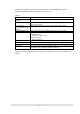
In addition to the application software embedded as standard above, this PA-2400W supports specific applications and functions described in the table below for business use. Table 1.2 Item MFC, VB runtime Software Automatic Setup Function Data backup and restoration with compact flash card FLCE, FCHKE in ROM Support libraries Display drivers Alarm startup prohibition Change of startup picture Operability Description Runtime modules for MFC and PVB are in ROM.
1.2 External View Fig. 1.
1.3 Specifications 1.3.1 Hardware Size Weight Battery Operating hours 179 mm (W) x 107 mm (D) x 21 mm (H) Approx. 370 g Lithium-ion battery pack (main battery) Alkaline batteries (LR6 x 2) can also be used as substitution. CR2032 x 1 + IVR2430 x 1 (sub-battery) Lithium-ion battery pack Approx. 10 hours (adequate for 90 Pocket Word strokes/minute) or Approx. 15 hours in “10:1” mode Alkaline batteries LR6 x 2 Approx. 10 hours (adequate for 90 Pocket Word strokes/minute) or Approx.
Fig. 1.3 System Configuration # $ !! & + 78 1 - % - 9 #% $ !! & + 78 $ % . / 0 / / $ # & ) $ * !" " &)+ ' " (% ) .
1.3.3 Basic Specifications CPU Hitachi 32-bit RISC Maximum operating frequency: 80 MHz Memory System ROM System RAM : Mask ROM : DRAM : 16 MB (OS: 8 MB x 2) : 8 MB Display Unit Number of pixels Touch panel Gradation Contrast adjustment Font : 480 x 240 (0.
1.3.4 Option Recommended options for PA-2400W can be found on the Microsoft Web pages for locally available options or by information available from CASIO for PA-2400W’s dedicated options. The user assumes all responsibility for the use of options recommended neither by CASIO nor by Microsoft.
2. Operation 2.1 System Configuration Table 2.
Operation Mode With PA-2400Ws via IrDA interface System Configuration Use of System Program transmission Data transmission Report print With PA-2400W and Handheld printer With PA-2400W and Bar Code reader Barcode input for product control With PA-2400W and LAN card, RF-LAN card Network Connection Intranet terminal Data transmission Mail client LAN 12
3. Bootup Procedure 3.1 Bootup Method The PA-2400W (Windows CE, Ver 2.11) will boot up in one of the following three ways: Cold-bootup Start If no data is stored in Object Store (e.g. in case the main or the sub-battery is to be replaced) and after the diagnosis program has been executed, a Power-ON start from "Power-On factor" will initialize Object Store, boot the OS, make user setups, and execute Welcome Wizard.
Battery is installed. File area is cleared. Cold-bootup (Battery is not installed) Work area is cleared. Warm-bootup (Reset SW) Device is ready for startup. Fig. 3.1 Bootup Process 3.2 Bootup with Special Key Sequence To aid maintenance or application development the following functions can be initiated depending on simultaneous key and switch operation. In case the bootup is done by this method, the RESET SW should be pressed last. Table 3.
3.3 Messages at Bootup Messages below will be displayed when a FULL RESET (with NotificationSW + Reset) is performed or if the status of memory is illegal. One of the messages is displayed to notify the user unstable system condition by illegal process in application program. Fig. 3.2 Message at full reset Fig. 3.3 Message at unstable memory status Fig. 3.
4. Power Control 4.1 Power-ON Factors Power-on factors include: The power is turned on by pressing the POWER SW. The power is automatically turned on at the specified time by the alarm function. The power is automatically turned on if the CD signal is detected by the PA-2400W connected to PC via the RS-232C cable. The power is automatically turned on when the PA-2400W is mounted on I/O Box.
4.4 Power Saving Process Auto Power OFF (APO) Automatically turns off the system if any action (key operation, touch panel operation, disk access operation, card access, or communication) is not performed in a given period of time. The software can set whether the APO function is enabled or disabled and the APO time. The APO time can be set to between 1 and 5 minutes, in 1 minute increments. Fig. 4.
4.5 Low Battery Level Monitoring For the PA-2400W there are three low battery levels available which can be used to detect low battery voltage. Table 4.1 Battery voltage monitoring levels Level Contents VDET1 Low main battery voltage alarm VDET2 Power off due to low main battery voltage Power off immediately due to low main battery voltage. Low sub-battery voltage alarm VDET3 VDETS Operation Next boot-up Indicates low main battery voltage alarm Turns off the power. --Resume Critical off.
4.6 Low Battery Voltage Alarm Indication The following alarm screen appears if the main battery or sub-battery voltage drops. Fig. 4.4 Low main battery voltage alarm screen Fig. 4.
4.7 Remaining Battery Voltage Indication The remaining battery voltage can be displayed if the Power Management icon or Battery icon is touched on the Control Panel. Fig. 4.6 Battery property display screen Note: The "LOW" indication also appears if a VDET1 event occurs, even if it occurs when the backlight is on. If the voltage is "Low" or "Very Low" the backlight can not be restored to ON. If the battery condition is reset by turning the power on and off, the "LOW" indication will be canceled. 4.
5. List of Software Products Available Table 5.
6. Input Method 6.1 Startup of SIP By pressing the SIP key, the software keyboard can appear and disappear. The SIP key toggles ON and OFF the software keyboard. Table 6.1 Key Function Description SIP Starts up and displays the software keyboard. LIGHT Turns ON and OFF the backlight. SIP + LIGHT Starts up the calibration mode. SIP : Software Input Panel 6.2 Software Input Panel (SIP) This software input panel can be initiated if the icon in the task bar is touched.
7. Fonts Only true type fonts can be used. It is possible to add more font types to the pre-installed fonts. To do this, use Mobile Devices to download the font from the Windows Fonts directory on the PC to the PA-2400W. This operation converts the original font via the font filter to a format that can be used on the PA-2400W. After download, switch to the desired font on the PA-2400W. Table 7.
8. Registry The following list shows the registry values that have special meanings on the PA-2400W. Default Setting of SIP keyboard [HKEY_LOCAL_MACHINE\Software\Apps\SIPManager] SIPExeName"="SIPanel.exe" SIPQuitOpt"="/q" Table 8.1 “SIPExeName "SIPNormOpt" “SIPQuitOpt" Description Name of a program that is started up when the SIP button is depressed. The user must change this default name to his own program name for his own SIP keyboard.
9. Application Development Environment 9.1 Overview User applications may be developed under the following development environment. Table 9.1 Application development environment Development platform Microsoft Windows NT4.0 +SP3 or later (English version) Development language Microsoft Visual C++ Ver6.0 + ToolKit for Visual C++ 6.0 Microsoft Visual Basic Ver6.0 + ToolKit for VisualBasic 6.0 HandheldPC Professional 3.
Flow-chart of Development Procedure Edit source code Edit resource. Compile/link X86 Debug Debug emulation Compile/link SH Debug Transfer debug module Remote tool/ Remote debug Execute debug Compile/link SH Release Transfer release module Execute PC side PA-2400W side Fig. 9.1 Software development procedure For more information refer to the Microsoft ToolKit and other reference manuals published separately for Windows CE.
10. Card Backup Tool 10.1 Overview This “Card Backup Tool” can back up object store area in RAM memory of the PA-2400W and user’s data to a compact flash card and can restore them. The following items can be backed up with this tool. File Registry CE data base (Reception tray, task, data of the address notebook) The methods to back up these data are “Manual Backup” and “Automatic Backup” which can be performed at a specified time. Notes: 1.
10.3 Installation of Card Backup Tool Installation from PC 1. First, close all application programs run on the PA-2400W before starting the setup program. 2. Install a PC card (or a compact flash card) into the PCMCIA card slot (or the compact flash card slot) where you wish to download the “Card Backup Tool” from PC. 3. Connect the PA-2400W to PC using cable while the power is switched on. It may take time to establish session between the PA-2400W and PC. 4.
10.4 Backup Operation Select “Card backup Tool” in the start menu and execute it. Fig. 10.1 Startup of Card Backup Tool To Backup Data Manually 1. Turn off the PA-2400W and install a memory card into the PCMCIA card slot (or compact flash card slot) of the PA-2400W. If both the cards, PCMCIA card and compact flash card, are being loaded, the card that specified as Storage Card will be used for destination folder. 2. Turn on the PA-2400W power and close any applications if running. 3.
Fig. 10.3 While executing Fig. 10.4 While aborting Fig. 10.
Fig. 10.6 Error message Fig. 10.
To Schedule Auto Backup 1. 2. 3. 4. 5. From the Start menu, select “Card Backup Tool” to execute the application. Input the time when you want Auto backup to be performed. Check the “Auto backup” checkbox. Tap the “Change auto backup settings” button. After you are finished with making the settings you want, click the close button in the upper right corner of the window to close the “Card Backup Tool”. 6.
Fig. 10.9 Error message (while end-user is operating) Fig. 10.10 Error message (not enough memory or a PC card is not loaded) Fig. 10.
10.5 Restoration 1. 2. 3. 4. 5. 6. 7. 8. 9. 10. Perform a FULL RESET operation to delete all data from the PA-2400W’s memory. Insert the compact flash card that contains the “Card Backup Tool” into the PA-2400W’s compact flash card slot. Use Explorer to navigate to the memory card, and then start up the “Card Backup Tool”. If the backed up data is on a different card, remove the card with the application and replace it with the card that contains the back up data.
Fig. 10.14 Error message (PC card is not loaded or no data to back up) Fig. 10.
10.6 Error An error message will appear if the followings occur in each performance of the manual backup, automatic backup and restoration. After appearance of the error message, solve the error and execute the performance again. Battery capacity is low. PC card (or compact flash card) is not loaded in the slot. PC card (or compact flash card) has not enough free memory capacity. No backup data existed (in the restoration performance). For error messages that appear refer to Chapter 10.
11. Automatic Setup Function 11.1 Overview In this chapter, method to install an application program by using the “Automatic Setup Function” is described. Often an application program is pre-installed by you before shipment to end-user. The application program once installed in the PA-2400W could be deleted accidentally by operator or because of the excess duration of battery life.
11.3 Notes If both compact flash card and PC card are being loaded in the PA-2400W and a reset is performed, a compact flash card installed in the compact flash card slot will become “\\Storage Card”. Suppose both “Storage Card” and “\\Storage Card2” are existed in the slots, and pull out the “Storage Card” and re-install it immediately, the “Storage Card2” can still be accessed.
12. Display Drivers Display drivers available from CASIO can consist of two different orientations, either Landscape or Portrait, versions of 90-degree, 180-degree and 270-degree. These display drivers are used to re-position the LCD screen of the PA-2400W at a tilted angle for such use as that for example the IrDA port to be located at the opposite direction (to right side). The drivers are provided in the development kit and can be found as following names. Table 12.1 File name of drivers DDI_90.
13. Restrictions with PA-2400W The followings are restriction and limitation that user of the PA-2400W may encounter while operating. The user must always be aware of them. Countermeasure against each restriction is also described for your reference. Compatibility of application software under Windows CE ver. 2.00 and ver. 2.11 Neither Microsoft nor CASIO assure you compatibility of application software.