IT-2000W (Windows version) Technical Reference Manual (Version 1.00 ) April 1998 Casio Computer Co., Ltd. Copyright ©1998. All rights reserved.
Table of Contents Chapter 1 1.1 1.1.1 1.1.2 1.1.3 1.1.4 1.1.5 1.2 1.2.1 1.2.2 1.3 Chapter 2 2.1 2.1.1 2.1.2 2.1.3 2.2 2.2.1 2.2.2 2.2.3 2.2.4 2.2.5 2.2.6 2.3 2.3.1 2.3.2 2.3.3 2.3.4 2.3.5 2.3.6 2.3.7 2.3.8 2.3.9 2.3.10 2.3.11 2.3.12 Chapter 3 3.1 3.2 3.3 3.4 3.5 3.6 3.7 3.8 3.
Chapter Chapter Chapter Chapter Chapter 3.10 3.11 3.12 3.13 3.14 3.15 3.16 3.17 4 4.1 4.2 4.3 5 5.1 5.2 5.2.1 5.2.2 6 6.1 6.2 6.3 6.4 6.5 7 7.1 7.2 7.2.1 7.2.2 7.3 7.3.1 7.3.2 7.4 7.4.1 7.5 7.5.1 7.5.2 7.6 7.6.1 7.6.2 7.7 7.7.1 7.7.2 7.8 7.8.1 7.8.2 7.9 7.9.1 7.9.2 7.9.3 7.9.4 8 8.1 8.2 8.3 8.3.1 8.3.2 8.3.3 8.4 8.4.1 YMODEM Utility FLINK Command System Date/Time Setup Command Prompt RAM Disk Size Change Disk Format System Initialization Password Entry MS-DOS Overview How to Write CONFIG.
8.4.2 8.4.3 8.4.4 8.5 8.5.1 8.6 8.6.1 8.6.2 8.6.3 8.6.4 Chapter APPENDIX APPENDIX APPENDIX 8.6.5 8.6.6 9 9.1 9.2 9.3 9.4 9.5 9.6 9.6.1 9.6.2 9.6.3 9.6.4 9.6.5 9.6.6 9.6.7 9.6.8 9.7 9.8 9.9 9.10 A B C Debugging Through Simulation Operation Check on IT-2000 (Using COM2KEY/XY) Installation of Application Program Simulation Driver System Driver Simulator (SysCall.
Preface The IT-2000 Technical Reference Manual (hereinafter referred to as this document) is provided to assist the user in developing programs to run on the Casio IT-2000 (hereinafter referred to as this terminal or IT-2000 or HT). Microsoft C/C++ Ver.7.0 or later, and the manuals supplied with it, is required to develop programs for this terminal. Read Chapter 1 of this manual in its entirety to understand the features of this terminal.
1. Overview 1.1 Features of System 1.1.1 Development Concept The IT-2000 is a data collection terminal for business use. After years of refinement Casio Computer Co., Ltd. has developed its hand-held type terminals so that they yield high speed and a high functionality in comparison to general personal computers. This allows improved efficiency in software development. It has adopted the IBM PC/AT architecture and incorporated an IBM PC/AT compatible BIOS. It uses MS-DOS Ver. 6.
PC card slot conforms to PCMCIA Release 2.1 supporting various PC cards. Implements IrDA 1.1 protocol for high-speed infrared communication. System menu makes it easy to maintain the IT-2000 and install user application programs. Provides various development support tools including C-language libraries and communication utilities for developing business application programs. 1.1.
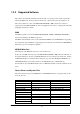
1.1.5 Model Name The following IT-2000s of Windows version will be available. For price of each model, please consult with your local Casio representative.
1.2 1.2.1 System Configuration Hardware Block Diagram CPU i486GX 1 Power switch MASK ROM FLASH ROM (DINOR) BIOS/DOS Battery voltage monitoring sensor DRAM A/D converter UART/ SIR Temperature sensor Illumination sensor COM 1 Buffer 8-pin Key RTC Keyboard controller Analog touch panel ASIC RTC IrDA Driver/Receiver IrDA 1.1 IrDA 1.
1.2.2 Supported Software The software used with this terminal can be divided into two categories: the system software that includes the BIOS, OS, and device drivers and the user software such as the development tools. The system software is stored on the DINOR FLASH ROM (1 MB), and the user software is supported from the SDK CD-ROM (version 4.0) supplied by Casio at free of charge. The following paragraphs describe the software. BIOS The BIOS program is stored in the DINOR FLASH ROM.
TFORMAT.EXE Basic drive (C:) F-ROM drive formatter Windows Driver These drivers are necessary for the Windows to run on IT-2000. Download to F-ROM drive (D: ). File name VGA_C.DRV VGA_NC.DRV PENMOUSE.DRV VKD.386 IRDA.DLL IRCOMM.DRV Storage location MASK ROM drive (E: ) Description Display drivers SDK SDK SDK Mouse driver Virtual key driver IR communication drivers Utilities For information about the utilities refer to Chapter 9 "Utility". File name WCAL.EXE WCALC.EXE WCLOCK.EXE WCHKBATT.EXE XY.
Development Tool Libraries All the libraries of Windows are provided either as Dynamic Link Library (DLL) or as Visual BASIC Custom Control (VBX). To use these libraries, download first to a directory in F-ROM drive (D: ). The files, *.LIB and *.H, are needed when you develop an application program. File name LIBSYSW.LIB SYSCALL.DLL SYSCALLP.DLL SYSLIB.H PADCTRL.VBX PADCTRL.H LIBOBR.LIB OBRLIB.H OBRLIB.DLL LIBYMOD.LIB YMODEM.DLL YMODEM.H FLINK.LIB FLINK.DLL FLINK.H COM2KEY.EXE PMON.COM PMOFF.
1.3 Precautions If reading the internal clock with INT21h the significant data should include and be limited to the seconds digits. On this terminal the time is read directly from the RTC so that the correct time can be attained at any moment, even during extended continuous use. As a result the 1/100 of a second digit is ignored. (refer to Chapter 7.3 “Clock Control Driver”.) To count time, the counter of DOS or the function provided for reading time must be used.
If an LB1 event (low main battery voltage) occurs, the alarm buzzer starts sounding and system operation is suspended about 10 minutes later. If the alarm buzzer starts sounding, terminate the current operation as soon as possible and recharge the main battery. This system will not execute an alarm indication to be displayed on the LCD screen for an LB2 event (low sub-battery voltage) or LB3 event (low SRAM card battery voltage).
The backlight is turned off by means of the ABO (Auto Backlight OFF) function. However, it is turned off 1.3 seconds after the setup time. This is because the system has 1.3 seconds of monitoring time before the internal timer is started. During the process of loading Windows after boot-up, do not press the Power switch.
2. Basic Software 2.1 Overview 2.1.1 Software Configuration The following diagram shows the software configuration of the IT-2000W. Application Program LibSYSW.LIB LibOBRW.LIB LibYMOD.LIB FLINK.LIB Mouse Event Display Req. VGA_NC.drv MS-Windows OBRLIB.DLL YMODEM.DL PADCTRL.VBX PenMouse.drv FLINK.DLL AT Architecture LibSYSW.LIB IrDA Driver & ROM BIOS SysCall.DLL VKD.386 Handy Terminal Original Hardware & ROM BIOS Fig. 2.
2.1.2 Memory Map The memory map of the IT-2000 is as follows. Extended Memory 100000h ROM BIOS NAND DISK BIOS/VGA BIOS Memory Mapped Disk I/F PC Card I/F EMS Windows 16 KB x 4 Reserved 0F0000h 0E0000h 0DC000h 0D8000h 0C8000h 0C0000h Video Buffer 128 KB 0A0000h System RAM 640 KB 000000h Fig. 2.
2.1.3 Drive Configuration The drive configuration differs for each model as described in the following table: Drive A: [Read and Write] Drive C: [Read Only] Drive D: [Read and Write] Drive E: [Read Only] Drive F: [Read Only] Drive G: [Read and Write] RAM disk This drive is prepared for use after the RAM disk size is specified from the System Menu. The contents of this RAM disk will not be erased through a boot process or by pressing the RESET switch.
2.2 Basic System Operation 2.2.1 Overview Basic operation of this system on the terminal consists of the suspend/resume process and boot process operated by means of the Power switch and RESET switch, as shown in the following diagram. OFF STATE ON KEY ON STATE Application BOOT OFF EVENT RESET SWITCH OFF EVENT System Menu BOOT OFF Process OFF Process ON EVENT ON Process System Menu RESET SWITCH System Menu BOOT SUSPEND STATE ON KEY System Menu BOOT INITIAL STATE Fig. 2.
The following table summarizes the power-on processes provided for this terminal. System Menu boot process Application boot process Resume process Always executes CONFIG.SYS and AUTOEXEC.BAT located in drive (C:) for starting up the MS-DOS. Searches for CONFIG.SYS and AUTOEXEC.BAT prepared by the user and starts up MS-DOS from the drive where they are located. Restores the memory conditions that existed before the power was turned off and continues operating according to the conditions.
2.2.2 Power ON Process Overview The ON process is provided to make the system ready for use (ON state). The actual process varies depending on the settings at that point in time and the last OFF factor (the cause of the OFF action).
System Menu Boot Process Press the RESET switch to set the drive C as the current drive, and load MS-DOS from that drive. As a result, the System Menu that includes the maintenance program will be initiated (refer to “System Menu Boot Process” on this page). Resume Process This process restores the conditions that existed before the power was most recently turned off. Any application program that was running at that point in time can be continued.
Note: The RESET switch can be used not only for initiating the System Menu but also as the forced restart switch when the user application program under development hangs. However, note that if the RESET switch is pressed while the disk is being written to, the data may be corrupted. Therefore, the RESET switch should be pressed only while the power is off. Clock data or information on the RAM disk will not be lost if the RESET switch is pressed.
This terminal has the Auto Power ON function which automatically starts the system. This Auto Power ON function can operate in one of the following three ways: Auto Power ON function (only affects the resume process) activated by alarm The system power can be turned on (resumed) at the specified time by means of an alarm. However, this will not function if the next start-up method is set to the boot process in the system library.
2.2.3 Power OFF Process Overview Turns off the system power. However, the power to all the devices is not turned off and some can be used for storing the information required for the next resume operation. This process is called the suspend process and the state of the system while off is called the suspend state.
OFF Factors The OFF factors refer to various causes that make the system enter the OFF state (suspend state), as follows: OFF factor Power switch Auto Power OFF (APO) Power OFF by Software Power OFF due to time-out of low battery voltage (LB1) alarm If main battery voltage falls to an inoperable level (LB0) Power OFF due to RESET switch pressed Description System operation can be suspended by holding down the Power switch for more than a second.
2.2.4 Battery Voltage Monitoring Process This terminal uses a main battery (lithium-ion battery pack) for driving the main unit, and a primary sub-battery (lithium battery) and a secondary sub-battery (lithium-vanadium battery) for backup. Application programs can acquire the status of these batteries through the APM BIOS or system library. Refer to Chapter 9.5 “Remaining Battery Voltage Display Utility”. Battery Operation Scheme The following diagram shows how each battery operates within the system.
Low Voltage Level The IT-2000 continuously monitors the voltage of the main battery, the primary sub-battery, and the SRAM card battery. This allows an application program to determine through the system library if the voltage of each battery reaches a warning level. The following table summarizes the low battery voltage warning levels, which application programs can acquire through the system library.
Main Battery Voltage Monitoring If the main battery voltage reaches LB1, the system issues a warning buzzer. If this warning buzzer sounds, either start recharging the battery or replace it with a fully charged battery as soon as possible. If one of these measures is not taken within ten minutes, the system will forcibly turn off the power for safety. The following diagram shows the main battery voltage against the time axis. Main Generate warning buzzer Battery Voltage level to operate.
Sub-battery Voltage Monitoring The sub-batteries are used for system backup while the main battery is being replaced. The subbatteries consists of two units: the primary sub-battery (button-type lithium battery) and secondary sub-battery (button-type lithium-vanadium battery). The secondary sub-battery is recharged by the voltage of the main battery.
2.2.5 Low Consumption Current Process This terminal has the APM BIOS installed to provide a low-power consumption capability. It works in combination with POWER.EXE from Microsoft Corporation. The low-power consumption capability is further enhanced by the use of unique power management functions, including Auto Power OFF (APO) function, Auto Backlight OFF (ABO) function, and DOZE/RUN transit function.
Auto Power OFF Function (APO) This function automatically shifts the system to the OFF state (suspend state) if no event has taken place for a specified period of time from the touch panel, the keyboard, COM1, or a file. This time interval has been set to one minute by default. It can be modified using the System Menu or system library.
DOZE/RUN Transit Function On this terminal the system will reduce the clock speed of the built-in CPU if no activity (access to the touch panel, keys, COM1, or file) has occurred for a specified period of time (four seconds). The state in which the CPU clock speed has been reduced is called the "DOZE state" and the state in which the CPU is operating at full speed is called the "RUN state". If an activity occurs in the DOZE state, the system returns to the RUN state.
2.2.6 How to Replace or Recharge Batteries Replacement of Batteries The method used to replace the main battery, sub-battery, and SRAM card battery are explained here Failure to observe the correct battery replacement procedure may result in a loss of data. Always observe the following steps in battery replacement. Main battery replacement Hold down the Power switch for more than one second to turn off the main unit power.
Note: The SRAM card is supplied power by the main battery when it is installed in the main unit. This means that the SRAM card can be used normally as long as it is in the slot, even if the voltage of the card battery is zero. In this case, however, the data on the SRAM card will be lost when the card is removed from the main unit slot. Since the Casio SRAM card is provided with two batteries, the data will not be lost a short while even if one of them is removed.
2.3 Supported Devices 2.3.1 Display Unit Hardware Configuration LCD Resolution Tone Method VRAM RAM for hardware window FSTN semi-transparent liquid crystal display 192 x 384 dots B/W 16 gray scales (4 gray scales are identifiable) VGA compatible 512 KB 32 KB Note: With B/W liquid crystal displays the actual display colors will be changed to reverse video. About the Display Screen Since this terminal has a VGA controller, it can internally control the entire VGA (640 x 480 dots) screen.
Software Functions Standard Video BIOS is supported.
2.3.2 EL Backlight Overview This terminal has the following functions to control the backlight. For more information refer to Chapter 6 “Keyboard Controller”. Manual Backlight ON/OFF function Auto Backlight OFF function (ABO) Auto Backlight Control function (ABC) Manual Backlight ON/OFF Function The backlight can be turned on and off with the following methods. Press the 7 key after the Fn key to turn on or off the backlight. Call the system library to turn on or off the backlight.
2.3.3 Touch Panel Hardware Configuration Method Resolution : Analog type touch panel : 192 x 384 dots Software Function To enable application programs to acquire touch panel coordinates, the following two pieces of software are provided: PENMOUSE.COM With this PENMOUSE.COM application programs can acquire touch panel input through the mouse I/F. (refer to Chapter 7.5 “PenMouse Driver”.) KEYPAD.EXE With this keypad driver application programs can perform character input through the touch panel.
2.3.4 Disk Types of Disk Type RAM disk Basic drive F-ROM disk PC card Drive name A C D G or F Capacity 0 to 1920 Kbytes 768 Kbytes 0, 4, 8, 12, 16 or 24 Mbytes SRAM card, ATA card Note: The drive name of the PC card varies for each model. For more information refer to Chapter 2.1.3 “Drive Configuration”. RAM Disk Part of the main RAM can be assigned on the RAM disk using System Menu.
F-ROM Drive The F-ROM drive is supported as a disk for which both read and write operations are possible (only for models with the F-ROM drive). Various disk capacities are supported for each model: Disk capacity: 0 (models without F-ROM), 4M, 8M, 12M, 16M or 24 MB. To format the F-ROM drive use the System Menu. For information about the formatting method refer to Chapter 3 “System Menu”. In this process the System Menu will call TFORMAT.EXE from drive (C:) to format the F-ROM drive.
2.3.5 Serial Communication Available Interfaces Port COM1 I/O Address 3F8h-3FFh Name 8-pin serial I/F COM2 2F8h-2FFh COM3 3E8h-3EFh Uses Connection with a barcode reader or PC 14-pin serial I/F Connection with an expansion I/F device IrDA 1.0 Communication with an I/O Box or between two IT2000s (Modem card) Modem card COM4 2E8h-2EFh IrDA 1.1 Communication with an I/O Box or between two IT2000s Remark Can be switched via the system library. If a modem card is used.
COM2 Either the 14-pin serial I/F or IrDA 1.0 can be assigned to this COM2 port depending on the system library setup. Both the 14-pin serial I/F and IrDA 1.0 can be used as a normal RS-232C interface. By default, the COM2 channel is not assigned to either device. Therefore, always use the system library to designate either the 14-pin serial I/F or IrDA, then turn on the power. The 14-pin serial I/F is located on the rear of the panel.
2.3.6 PC Card Hardware Overview Standard Register compatibility Slot Power supply Card lock switch Conforms to PCMCIA Release 2.1 Has register compatibility with Intel 82365SL Step 1 slot TYPE II Vcc : 5V (not operable at 3.3V) Has a card lock switch Recommended PC Cards Type SRAM card ATA Flash ROM card Model DT-635MC (256 KB) DT-636MC (512 KB) DT-637MC ( 1 MB) DT-9031FMC ( 2.
Card Lock Switch The IT-2000 has a card lock switch to prevent accidental removal of the card. Any card can be made usable only after it has been inserted in the slot and the switch has been locked properly. However, since some types of cards do not allow this card lock switch to be closed, a library routine to disable this switch is supported. For more information refer to Chapter 8.6.2 "System Library”.
2.3.7 Clock Timer Clock BIOS 00h to 07h of the INT1Ah function is compatible with the IBM PC/AT. Since INT1Ah can be called in the C language, an alarm operation using the clock can be set with the system library. Alarm If an alarm operation is set using the INT1Ah or system library, it is possible to cause an INT4Ah interrupt at the specified time to issue the alarm.
2.3.8 Buzzer This terminal is provided with a buzzer function that is compatible, via an appropriate interface, with the IBM PC. The application side can sound this buzzer by controlling the I/O port assigned to 61h. It is also possible to modify the sound frequency by controlling channel 2 of the timer. For information about the method used to modify the frequency refer to the hardware manual of the PC/AT compatible machine.
2.3.9 Barcode Reader Overview The IT-2000 supports the following two Casio OBR (Optical Barcode Reader) models: DT-9650BCR ( Pen scanner ) DT-9656BCR ( CCD scanner) Connect the OBR to the COM1 (8-pin) port of this terminal, and set up the interface as follows. Synchronization Baud rate Data bit Parity bit Stop bit Asynchronous 9600 bps 8 bits none 1 bit For communication between the OBR and this terminal use the OBR library.
2.3.10 Infrared Communication (IR) The infrared communication function of this terminal supports the protocol of IrDA 1.0 (see note below) and IrDA 1.1 standards. IrDA 1.0 can be used as the COM port for a general RS-232C. IrDA 1.1 can provide communication at a maximum rate of 4 Mbps by means of the dedicated utility (FLINK utility). IrDA 1.0 Item Synchronization Baud Rate COM Port Specification Asynchronous 115.2 Kbps max. COM2 Remark Conforms to IrDA1.
2.3.11 Keys Hardware Overview Key configuration IRQ Key repeat function Simultaneous pressing of multiple keys Roll-over function 5 (column) x 3 (row) keys IRQ1 available not available not available Key Layout See the following key layout. Fn 7 8 9 - 4 5 6 CLR 0 1 2 3 Fig. 2.12 Fn key The "Fn" key should be used in combination with the numeric key. Hold down the "Fn" key and press a numeric key.
2.3.12 Sensors The IT-2000 has the following three types of built-in sensors: Illumination sensor Temperature sensor Battery voltage level sensor Attached to the upper section of this terminal and used to sense the ambient light intensity. It is used for the Auto Backlight Control (ABC) function. It cannot be controlled directly from the application. (For more information about the system library refer to Chapter 6 “Keyboard Controller”.
3. 3.1 System Menu Overview The system menu is a program and used to perform various setups (system clock, contrast of liquid crystal display, etc.) and implement (downloading) application programs, all of which are necessary to use this terminal. To start up the system menu press the reset switch located at the back of the main unit. When the reset switch is released a short beep will sound and, after a short while, a screen as shown in Fig. 3.1 will appear.
3.2 Basic Operation In the system menu a common set of key operations are used. The following list shows the keys that can be used in the system menu. Current Condition Line cursor is on Key Operation 8 2 CLR RET Others 0 to 9 RET CLR Operation Process Moves the line selection cursor up one line. Moves the line selection cursor down one line. Moves the line selection cursor to the upper menu area, if it is located in the lower menu area. Confirms and executes the currently selected menu item.
3.4 Key Click Sound Setup Function Sets the key click sound ON and OFF. If it is set to ON, a key click sound is heard when a key is pressed or when the keypad is touched. It does not sound if it is set to OFF. Fig. 3.3 Operation Select ON/OFF with the “ 0” or “ 1 “ key, then confirm the selection with the “RET” key. Key Operation 0 key 1 key . (decimal) key RET key CLR key Others Function Sets the key click sound to OFF. Sets the key click sound to ON. Toggles to ON and OFF of the key click sound.
3.5 Buzzer Volume Setup Function Sets the volume of the buzzer (beep). One of the four levels (OFF/Small/Medium/Large) can be selected. Fig. 3.4 Operation Make a selection with a key, “ 0” to “ 3 “, and confirm the selection with the “ RET” key. Key Operation 0 to 3 keys . (decimal) key RET key CLR key Others Function Selects the corresponding number. Toggles between two selections. Confirms the currently selected setup and exits this operation.
3.6 Contrast Adjustment Function Adjusts the contrast of the liquid crystal display. Fig. 3.5 Operation Press the “8 “ key to increase the contrast or press the “ 2” key to decrease the contrast. Press the “ RET” key to confirm the setting. Key Operation 8 key 2 key RET key CLR key Others Function Increase the contrast. Decrease the contrast. Confirms the currently selected contrast setup and exits this operation. Cancels the currently selected contrast setup. Invalid.
3.7 Auto Backlight Setup Function Sets the auto backlight control ON or OFF (refer to Chapter 6 “Keyboard Controller"). Fig. 3.6 Operation Select ON/OFF with the “ 0” or “ 1” key, then confirm the selection with the “RET” key. Key Operation 0 key 1 key . (decimal) key RET key CLR key Others Function Turns the auto backlight control to OFF. Sets the auto backlight control to ON. Toggles to ON and OFF of the auto backlight control. Confirms the current setup and exits this operation.
3.8 Auto Power OFF Setup Function Sets the time-out period of the auto power off function (APO) (refer to Chapter 2.2.3 “Power OFF Process"). This time-out period is the interval between when no key entry or no entry on the touch panel is made and when the power of system is shut off automatically. Fig.3.7 Operation Set the APO time out period with the “ 2” or “ 8 “ key, then confirms the setting with the “ RET” key.
3.9 Touch Panel Calibration Function Adjusts the calibration of touch panel. If an inconsistency is noted between the target position and the position actually touched on the touch panel, correct it by performing this calibration adjustment. Fig. 3.8 Operation Adjustment of the calibration : with the stylus provided. the center of this in the upper left corner of the screen, then touch First make sure that the arrow points to When the buzzer sounds, release the stylus from the touch panel.
Note: If an mark does not disappear and the arrow does not move to the next position even if the mark has been touched by the stylus, an incorrect position was likely touched. Touch the correct position. Key Operation 1 key 2 key Others Function Adjusts the touch panel calibration starting from the beginning. Returns to the menu screen.
3.10 YMODEM Utility Function Used to achieve a file transfer via the COM cable. Communication can be established either between an AT-compatible machine (PC) and an IT-2000 (main unit), referred to as "PC-to-HT communication". A dedicated 9-pin DSUB-8-pin cross-type cable (DT-9689AX) is required to connect both the terminals. This utility does not have functions to allow communication between HT and HT. Use the FLINK function for the HT-to-HT communication. Fig. 3.9 Fig. 3.10 Fig. 3.
Note: When the cable comes off while the communication takes place: If the connection cable is accidentally unplugged while communication between the IT-2000 and PC is taking place, a communication error results and communication is interrupted. In this case the communication software on the PC will display an error message and interrupt transmission/reception, however, some data may remain in the transmission buffer.
Operations (1) SEND FILE TO HT (one file transmission from IT-2000 to IT-2000) This function may be available in future (as of now, not available). It is not allowed to use the function. If the file transmission between IT-2000s is needed, FLINK utility may be used (refer to Chapter 3.11 “FLINK Command”.). (2) SEND FILE TO PC (one file transmission from IT-2000 to PC) This function is used to copy an optional file from an IT-2000 to PC. To do this, use commercial terminal emulation software on the PC side.
When the "Normal End" message is displayed on the IT-2000 side, file reception has been completed. For information about the copy destination directory refer to the following table. If the “CLR” key is pressed during communication, file reception will be interrupted. It will take about 10 seconds for communication to completely stop. The following table shows the possible destination drive/directory for copy purposes.
3.11 FLINK Command Function Files can be transferred by infrared communication (IR). This can be implemented either as PC-toHT (AT-compatible machine to IT-2000) communication or as HT-to-HT (between two IT-2000 terminals) communication. To perform PC-to-HT communication an I/O Box for IT-2000 and a PC-side communication utility "LMWIN.EXE" is required. Fig. 3.13 Fig. 3.12 Fig.3.
Note: If the identical file name exists on the reception side, this command overwrites the existing file. At this time, the system does not unconditionally overwrite the existing file but creates a temporary file on the reception-side disk and attempts the overwrite after file transmission has been competed. This protects file data even if transmission of the file fails.
Note: If the “CLR” key is pressed during file transfer, transfer will be interrupted. It will take about 10 seconds for communication to completely stop. REMOTE SERVER (remote server mode ) The remote server mode is used by the system which assigns the right of issuing a transmission request to the partner side and enters the wait state for a request from the partner. To facilitate communication between two IT-2000 terminals, set the reception side to this mode.
3.12 System Date/Time Setup Function This is used to set (modify) the date and time of the built-in timer in the IT-2000 unit. Fig. 3.15 Operation Enter in the following order: year -> month -> day -> hour -> minute. Press a numeric key and the corresponding number will appear in the cursor position. Press the “ RET” key to advance to the next setting. If the “RET” key is pressed without making a numeric entry, the cursor will advance to the next setting without affecting the previous value.
3.13 Command Prompt Function This is the MS DOS command prompt screen. An appropriate DOS command can be inputted through the keypad. This DOS command prompt is the result of calling COMMAND.COM as a child process from the system menu. Consequently, if the EXIT command is entered, operation returns to the system menu. Fig. 3.
3.14 RAM Disk Size Change Function This screen is used to set the RAM DISK size (capacity). The setting will become valid after the system has rebooted. Fig. 3.17 Operation Setting up the RAM disk Adjust the RAM disk size with the “8” and “2” keys. Confirm the setup with the “ RET” key. When the "Hit Any Key... " message is displayed, press any key other than the “Fn” key. The IT-2000 is turned off. After making sure that it turns off, press the reset switch on the IT-2000 again.
Key Operation 8 key 2 key RET key CLR key 1 key 0 key Others Function Increases the RAM disk size. Decreases the RAM disk size. Confirms the currently selected RAM disk size and exits this operation. Cancels the currently selected RAM disk size. Formats the RAM disk (Format confirmation screen). Aborts formatting of the RAM disk. Invalid. Operations with the touch panel are not permitted.
3.15 Disk Format Function Formats the RAM disk and F-ROM drive. Fig. 3.18 Operation In the screen shown above, use the “2” or “8” key to select whether the RAM disk or user drive is to be formatted, then press the “RET” key. This makes the following screen appear. In this screen press the “1” key to move the cursor onto "YES" and press the “RET” key to start formatting.
Key Operation 2 or 8 key 0 key 1 key . (decimal) key RET key CLR key Others Function Selects the objective item (drive selection screen). Does not perform formatting (formatting start screen). Starts formatting (formatting start screen). Toggles YES and NO options of formatting. Confirms the current setting. Cancels the current setting. Invalid.
3.16 System Initialization Function Sets all the system setups to their default settings. Fig. 3.21 Operation The following table shows the available key operations. Key Operation 0 key 1 key . (decimal) key RET key CLR key Others Function Does not initialize the system. Initializes the system. Toggles YES and NO options of initialization. Confirms the current setting. Cancels the current setting and exits this operation. Invalid.
3.17 Password Entry Function When "FILE TRANSFER" or "MAINTENANCE" is selected for the first time after the system menu is initiated, the operator is requested to enter a password. Fig. 3.22 Operation With the keypad enter "system" (lowercase letter), then press the “RET” key. If the “CLR” key is pressed without entering a character, the password entry operation will be canceled.
4. MS-DOS 4.1 Overview In general, if a personal computer is booted-up with a floppy disk in the drive, first an attempt will be made to read MS-DOS from the floppy disk, and if a copy of MS-DOS does not reside on the floppy it is loaded from the hard disk (C:). However, this method cannot be used on this terminal since its basic drive (C:), which corresponds to the hard disk of a PC, is defined as a read-only device.
As described above, if the system power is turned on without an application installed (i.e. the conditions just after purchase), the CONFIG.SYS and AUTOEXEC.BAT files locating on the basic drive will be executed automatically. This inevitably initiates the System Menu (maintenance program). Therefore, if not only CONFIG.SYS and AUTOEXEC.BAT, but also an application program are installed on the user drive, it is possible for the application program to be automatically initiated from the user drive.
4.2 How to Write CONFIG.SYS and AUTOEXEC.BAT This section explains how to write the CONFIG.SYS and AUTOEXEC.BAT files mentioned in the previous section. A basic explanation of the CONFIG.SYS and AUTOEXEC.BAT is not given here. For further information about these files refer to the MS-DOS manual or appropriate technical documents. Observe the following notes when writing a CONFIG.SYS file. The System Driver (SYSDRV.SYS) is required to operate this terminal.
(1) DOS=HIGH,NOUMB This specifies that the main part of DOS is to be loaded in the HMA and, consequently, the UMB (Upper Memory Block) is not used. This terminal does not support a memory space for UMB if the EMS memory is to be used. Therefore, always specify NOUMB when using the EMS. (2) DEVICE=C: SYSDRV.SYS This driver is required to operate this terminal. Always install it before all other drivers. (3) DEVICE=C: HIMEM.SYS /M:2 Never fail to specify the "/M:2" option. (4) POWER.
Example of AUTOEXEC.BAT The following example shows a typical AUTOEXEC.BAT script. Since this example assumes that the system is booted from either the RAM disk or the NAND F-ROM drive, it is necessary to partially modify it if booting up from the ATA card. For information about booting from the ATA card refer to Chapter 4.3 "Card Boot". 1: C: ENDATA 2: C: CASIOAPM 3: (Environment variables setup and application call, etc.
4.3 Card Boot Basically the "card boot" operation boots MS-DOS from the ATA card, just like it is booted from a floppy disk. For this terminal the boot operation looks the same as this case. However, this terminal uses a boot process greatly different from a general card boot so that the MS-DOS in the drive C is always loaded, in such a way that MS-DOS not residing in the card is booted. Usually, in order to access the ATA card, a specific card driver is required.
the drive G, which is currently enabled, will be disabled. This problem arises from the fact that the hardware conditions established by initialization with CARDID.EXE are lost since access to the drive F was executed by means of specific codes included in the BIOS. To avoid this problem, these specific codes in BIOS should be disabled. ENDATA.COM is used to do this. If ENDATA.
CONFIG.SYS which resides on the drive C. However, CARDID.EXE cannot be registered as a device driver at a card boot. If this CARDID.EXE is registered as a device driver, two drives may be enabled concurrently if MS-DOS executes CONFIG.SYS. In addition, if ENDATA.COM is called with the INSTALL command, the drive G is enabled exclusively.
5. 5.1 MS-Windows Overview The MASK ROM drive (E:) of this terminals has MS-Windows installed in it. However, MS-Windows cannot be booted directly from this MASK ROM drive. This is because MS-Windows will overwrite some of the INI files at start up. However, since all files including the INI files are initially located in the MASK ROM drive, they cannot be overwritten, therefore an error will result.
5.2 Installation of MS-Windows As explained on the previous page, it is necessary to move (copy) some files onto the write-permit drive before booting MS-Windows. This section will describe this copy operation The following is an example of manually installing necessary files so that the user can determine the contents. A utility program (WINST.EXE) can be used to reduce the work load. For more information about this installation utility refer to Chapter 9.10 "Windows Installation Utility". 5.2.
Note: LOCAL may be released as SDK. If this is the case, use the files in SDK instead of those stored in E: WINDOWS LOCAL. The contents of the latest version of E: WINDOWS 5.2.2 Application Installation For this terminal it is recommended to initiate the application program at the same time MS-Windows is started. This can be achieved by modifying the shell line included in the “boot” section of system.ini. The default setup script of this shell line is "shell=progman.
6. 6.1 Keyboard Controller Overview This terminal is equipped with a sub-CPU dedicated to controlling the keyboard, touch panel, backlight, and various sensors. This chapter describes major tasks assigned to this sub-CPU. LCD Brightness El Backlight Temperature Sensor Main CPU Command Sub-CPU Illumination Sensor Data Battery Voltage Sensor Buzzer Volume Touch Panel Fig. 6.
6.2 Keyboard Control The keyboard control of IT-2000 is compatible with the IBM PC/AT. The keyboard controller senses if a key has been pressed and sends a MAKE or BREAK code to the main CPU. Application Program Primary/Secondary Code Function Process BIOS Hardware Interrupt Process Keyboard Input Buffer System Scanning Code Sub-CPU Keyboard Fig. 6.
Secondary code Basically a system scan code is assigned to each key, however, for some keys, different codes will be assigned depending on the Fn key. Code Table The following diagram shows the relationship between the keyboard keys and primary codes. Fn 7 8 9 - 4 5 6 CLR 0 1 2 3 37 38 39 2D 2E 34 35 36 1B 30 31 32 33 0D Fn key not pressed 003E 003F 0040 0044 003B 003C 003D Fn key pressed Fig. 6.
6.3 Touch Panel Control Function The keyboard controller has incorporated a program for acquiring the touch coordinates of the touch panel. This program compensates these acquired coordinates with the values obtained through calibration so that correct coordinate values can be calculated. The calculated coordinates will be passed to a ROM-resident program called PEN BIOS when mouse interrupt occurs.
6.4 Sensor Control This terminal has the following three types of sensors installed to serve as dedicated devices for handy terminal. Sensor Temperature sensor Illumination sensor Remaining battery voltage sensor Purpose of Use Detects the temperature inside the main unit. This result will be used to automatically compensate the LCD brightness. Detects the ambient light intensity to automatically turn on and off the backlight.
6.5 Backlight Control This terminal has incorporated two types of automatic backlight control functions: ABO (Auto Backlight OFF) and ABC (Auto Backlight Control). The ABO function is used to turn off the backlight if no key or touch panel input has been made for a given period of time, and the ABC function is used to automatically turn on and off the backlight depending on the intensity of the ambient light. These operations are performed by the keyboard controller.
Transition of Backlight Control Methods The concept of ABC lies in automating user operations. However, automatic control depends on the illumination sensor. It cannot be perfect because various types of light, sunlight or room light for example, may be incident to the sensor. Consequently, this requires manual ON/OFF control even if under ABC control. This leads to a further problem wherein the user may forget to turn it on or off.
1 ABC disabled Backlight ON state ABC disabled Backlight OFF state ABC enabled Backlight ON state ABC enabled Backlight OFF state ABC temporaril y disabled Backlight ON state ABC temporaril y disabled Backlight OFF state 2 3 4 5 6 Press F7 key 2 ABO time-up 2 ABC Enable 3 or 4 ABC Disable --- Becomes dark Ignore Becomes light Ignore Ignore Ignore *1 1 --- 3 or 4 --- *1 6 Ignore Ignore 2 5 --- Ignore 2 3 --- Ignore 2 3 --- 4 3 *3 3 --- --- 4 *4 Ignore 2 --- 4 *4 No
7. 7.1 Drivers Overview The following drivers are supplied for this terminal. Install them as required for operation. Driver System driver File name SYSDRV.SYS Clock control driver TIME.SYS Hardware window manager Keypad driver HWWMAN.EXE PenMouse driver PENMOUSE.DRV Virtual keyboard driver VKD.386 System library SYSCALL.DLL Display driver VGA_C.DRV VGA_NC.DRV KEYPAD.EXE Purpose Driver required to operate the system. This driver must be installed.
7.2 System Driver 7.2.1 Function The system driver (SYSDRV.SYS) must be installed because it executes critical processes in this terminal. The system driver mainly performs the following processes. LB1 monitoring and warning Monitors the main battery conditions and sounds a warning buzzer if an LB1 event is detected. It also forcibly turns off the system, if the battery voltage has not recovered within ten minutes of the buzzer sounding.
7.3 Clock Control Driver 7.3.1 Function This driver adjusts the system time on this terminal. This driver must be installed. On a general PC a timer interrupt occurs every 55 ms to update the clock tick counter, which is one of the BIOS system variables, and the clock overflow counter. The clock tick counter is incremented each time the timer interrupt occurs and read out from the real-time clock (RTC) when the PC power is turned on, and disappears when the power is off.
7.3.2 Startup Method This driver is loaded by defining the DEVICE statement in the CONFIG.SYS file. TIME.SYS is stored in the basic drive (C:). Format DEVICE=C: TIME.SYS Start option None Note: TIME.SYS must be loaded immediately after POWER.EXE.
7.4 Keypad Driver/Hardware Window Manager 7.4.1 Function The keypad driver (KEYPAD.EXE) is used to add the keypad function to the system. Application programs can use the keypad by calling the keypad driver functions via the keypad library (refer to Chapter 8.6.3 “Keypad Library”). This keypad driver internally calls the hardware window manager that enables the use of the hardware window. Therefore, the use of the keypad driver requires the residence of the hardware window manager.
7.5 PenMouse Driver 7.5.1 Overview The PenMouse driver (PENMOUSE.DRV) simulates the operation of the mouse driver specific to the personal computer using inputs received from the touch panel. The PenMouse driver makes it possible to run an application on the IT-2000 terminal that was designed for use with a mouse driver on the personal computer. However, perfect simulation cannot be achieved because of the physical difference between the mouse and touch panel.
7.5.2 Startup Method The PenMouse driver can be loaded by specifying as follow at [boot] section of SYSTEM.INI. However, it is loaded automatically to F-ROM drive (D: ) when Windows is installed by using the Windows installer. SYSTEM.INI is also created automatically. The driver is supplied as an SDK. Format: [boot] ...... mouse.drv=penmouse.drv Note: If the above format is deleted from SYSTEM.INI or from PENMOUSE.DRV, the mouse operations on Windows cannot be performed.
7.6 Virtual Keyboard Driver 7.6.1 Function The Virtual Keyboard Driver (VKD.386) is a driver that enables access to the keyboard controller on Windows (refer to Chapter 6 "Keyboard Controller"). This driver is only called from the system library. Since this driver has no chance of being directly called from the application program, the user does not have to be aware of its existence. Some of the system libraries use the functions of the keyboard controller.
7.6.2 Startup Method The Virtual Keyboard Driver can be loaded by making the following specification in the “386Enh” section of SYSTEM.INI. VDK.386 is included in SDK. If Windows is installed by the installer, VDK.386 will be automatically copied into the F-ROM drive (D:) and SYSTEM.INI will also be automatically created. Therefore, the user does not have to be concerned with this setup process. Format: [386Enh] ..... keyboard=vkd.386 Note: If the above script is deleted from SYSTEM.INI or if VDK.
7.7 System Library (main program file) 7.7.1 Function SYSCALL.DLL is a dynamic link library that constitutes the main program of the system library (refer to Chapter 8.6.2 "System Library"). Before executing an application that calls the system library it is necessary to locate this file in the Windows directory (or other directory to which the path is established). Some of the system libraries use the functions of the keyboard controller. However, Windows applications cannot directly access the hardware.
7.8 Display Driver 7.8.1 Function Display driver (VGA_C.DRV, VGA_NC.DRV) is a Windows display driver for a screen size of 192 x 384 dots. If this driver is used, maximized or iconized windows will not extend beyond the screen size and dialog boxes can be displayed in the center of the screen. The relationship between the Display driver and application programs is shown in the following diagram. Application Program Windows Display Driver VGA Controller LCD Display Fig. 7.
Note: If the above script is deleted from SYSTEM.INI or PENMOUSE.DRV is removed, no display operation is permitted on Windows.
7.9 COM Driver for IrDA 7.9.1 Overview The IrDA Driver consists of IRDA.DLL and IRCOMM.DRV. The former is processes the protocol section and the latter processes the port emulation and frame sections. It is possible to set up parameters to define the operation of the IrDA section by writing them in the WIN.INI file. Application Windows API Port Emulation Layer IRCOMM.DRV IrCOMM Layer TTP Layer IRDA.DRV IrLAP/IrLMP Layer IRCOMM.DRV Frame Layer SIR FIR Fig. 7.
IrCOMM Layer (including TinyTP Layer) The IrCOMM (Infrared COMM) layer includes TinyTP (Tiny Transport Protocol) layer. IrDA protocol can be used through this IrCOMM (TinyTP) layer. Three connection methods are supported: 3-Wire Raw, 3-Wire, and 9-Wire. The credit size of TinyTP is fixed to five (and it cannot be modified). 3-Wire Raw 3-Wire 9-Wire Can only perform transmission/reception of user data.
7.9.2 Windows 3.1 Communication Functions To perform communication with IrDA use API of MS-Windows. The following table lists the specifications of the available communication functions.
BuildCommDCB int BuildCommDCB(lpszDef, lpdcb) LPCSTR lpszDef; /* Address of the device control character string */ DCB FAR *lpdcb; /* Address of the device control block */ The BuildCommDCB function converts the device definition character string to the corresponding serial device control block (DCB) codes. < Parameter > lpszDef: Pointer to a character string that specifies the device control information and ends with a NULL character.
ClearCommBreak int ClearCommBreak (idComDev) int idComDev; /* Device with canceled break state */ The ClearCommBreak function cancels the break state of the communication device and restores it so it is ready for character transmission. < Parameter > idComDev: Identifies the communication device for which the break state is to be canceled. The OpenComm function will return this value. < Return value > Returns zero if the function is terminated normally.
CloseComm int CloseComm(idComDev) int idComDev; /* Device to be closed */ The CloseComm function will close the specified communication device and release the memory area assigned to the transmission and reception queues of the device. All characters in the transmission queue will be flushed out before the communication device is closed. < Parameter > idComDev: Specifies the device to be closed. The OpenComm function returns this value. < Return value > Returns zero if the function is terminated normally.
EnableCommNotification BOOL EnableCommNotification(idComDev, hwnd, cbWriteNotify, cbOutQueue) int idComDev; /* Communication device identifier */ int hwnd; /* Handle of window that receives the message */ int cbWriteNotify; /* Number of bytes written before notification */ int cbOutQueue; /* Minimum number of bytes of the output queue */ EnableCommNotification will enable or disable the posting of the WM_COMMNOTIFY message to the specified window.
Note: If the application specifies -1 for the cbWriteNotify parameter, the WM_COMMNOTIFY message will be sent to the specified window in the case of CV_EVENT notification or CN_TRANSMIT notification, but it will not be sent in the case of CN_RECEIVE notification. If the application specifies -1 for the cbOutQueue parameter, CV_EVENT notification or CN_RECEIVE notification will be made, but CN_TRANSMIT notification will not be made.
EscapeCommFunction LONG EscapeCommFunction(idComDev, nFunction) int idComDev; /* Identifier of the communication device */ int nFunction; /* Code of the expanded function */ The EscapeCommFunction is used to specify the communication device used to execute the expanded function. < Parameter > idComDev Specifies the communication device used to execute the expanded function. The OpenComm function returns this value. nFunction Specifies the function code of the expanded function.
FlushComm int FlushComm(idComDev, fnQueue) int idComDev; /* Identifier of the communication device */ int fnQueue; /* Queue to be flushed */ The FlushComm function is used to flush out all characters from the transmission queue or reception queue of the communication device. < Parameter > idComDev: Specifies the communication device to be flushed. The OpenComm function returns this value. fnQueue: Specifies the queue to be flushed.
GetCommError int GetCommError(idComDev, lpStat) int idComDev; /* Communication device ID */ COMSTAT FAR *lpStat; /* Address of the device status buffer */ The GetCommError function is used to acquire the last error value and current status of the specified device. If a communication error occurs, Windows will lock the communication port until the GetCommError function cancels the error. < Parameter > idComDev: Specifies the communication device for which the status is to be checked.
CE_TXFULL Not supported at present. The data will be passed from the transmission queue to the transmission buffer according to the IrDA protocol. It will be performed asynchronously with the write timing of the transmission queue by the WriteComm function. For example, if 2 kilobytes of data is written in a transmission buffer 2 kilobytes in size, the transmission buffer becomes full. This function is not supported because it is considered inappropriate for CE_TXFULL to be used in such a case.
COMSTAT structure typedef struct tagCOMSTAT { /* cmst */ BYTE status; /* transfer status */ UNIT cbInQue; /* Number of characters in the reception queue */ UNIT cbOutQue; /* Number of characters in the transmission queue */ } COMSTAT; The COMSTAT structure is used to store information about the communication device. < Members > status Indicates the transfer status. This member consists of the following flags. CSTF_CTSHOLD Not supported CSTF_DSRHOLD Not supported. CSTF_RLSDHOLD Not supported.
GetCommEventMask UNIT GetCommEventMask(idComDev, fnEvtClear) int idComDev; /* Communication device ID */ int fnEvtClear; /* Event to be cleared in the event word */ The GetCommEventMask function will acquire the bit specified by the fnEvtClear mask in the event word, then clear it. < Parameter > idComDev : Specifies the communication device for which the event word is to be checked. The OpenComm function returns this value. fnEvtClear: Specifies the event to be cleared in the event word.
OpenComm int OpenComm(lpszDevControl, cbInQueue, cbOutQueue) LPCSTR lpszDevControl; /* Address of the device control information */ UNIT cbInQueue; /* Size of the reception queue */ UNIT cbOutQueue; /* Size of the transmission queue */ The OpenComm function will open the communication device. < Parameter > lpszDevControl: Pointer to a character string that ends with a NULL. This character string is the device name in the format of COMn (n denotes the device number).
Note on IrDA: The OpenComm function does not support the LPT device. Since the OpenComm function does not control the power block of IrDA, the user should turn the power block to ON before executing this function. On the IT-2000 the IrDA interface is assigned to COM2 port, therefore the COM2 port should be specified. The OpenComm function operates differently depending on whether the terminal operates as the primary station or the secondary station. The WIN.INI file is used to specify the station type.
GetCommState int GetCommState(idComDev, lpdcb) int idComDev; /*Communication device ID */ DCB FAR * lpdcb; /* Address of the device control block structure */ The GetCommState function will acquire the device control block of the specified device. < Parameter > idComDev: Specifies the device for which the DCB is to be checked. The OpenComm function returns this value. This is a pointer to the DCB structure that receives the current device control block.
ReadComm int ReadComm(idComDev, lpvBuf, cbRead) int idComDev; /* ID of the device to be read */ void FAR * lpvBuf; /* Address of the buffer from which bytes are read */ int cbRead; /* Number of bytes to read */ The ReadComm function will read the byte data from the specified communication device and assume the specified number is the maximum bytes. < Parameter > idComDev: Specifies the device to be read. The OpenComm function returns this value.
SetCommBreak int SetCommBreak(idComDev) int idComDev; /* Device to interrupt communication */ The SetCommBreak function is used to interrupt character transmission and set the communication device to the break state. < Parameter > idComDev: Specifies the communication device to be interrupted. The OpenComm function returns this value. < Return value > Returns zero if the function is terminated normally. Otherwise a value less than zero will be returned.
SetCommEventMask UNIT FAR *SetCommEventMask(idComDev, fuEvtMask) int idComDev; /* Communication device to be enabled */ UNIT fuEvtMask; /* Event to be enabled */ The SetCommEventMask function will enable the event included in the event word of the specified communication device. < Parameter > idComDev Specifies the communication device to be enabled. The OpenComm function returns this value. fuEvtMask Specifies the event to be enabled. This parameter consists of any combination of the following values.
Note: The application must enable the event using the SetCommEventMask function before the GetCommEventMask function records the occurrence of an event. If the communication device event shows a line status error, the application should call the GetCommError function after calling the GetCommEventMask function. Note on IrDA: Some of the events are not supported at present.
SetCommState int SetCommState(lpdcb) const DCB FAR * lpdcb; /* Address of the device control block */ The SetCommState function will set the communication device to the state that is specified by the device control block. < Parameter > lpdcb: Pointer to the DCB structure that stores the communication settings for the device. Specify the device name for the Id member of the DCB structure. < Return value > Returns zero if the function is terminated normally. Otherwise it returns a value less than zero.
DCB structure /* DCB */ typedef struct tagDCB { /* internal device ID */ BYTE Id; UNIT BaudRate; /* Baud rate */ BYTE ByteSize; /* Number of bits per byte (4-8) */ BYTE Parity; BYTE StopBits; /* 0 = None, 1 = Odd, 2 = Even, 3 = Mark, 4 = Space */ /* 0 = 1 bit, 1 = 1.
The DCB structure defines the control setups of serial communication. < Members > Id Identifies the communication device. This value is set by the device driver. If the most significant bit (MSB) is set, the DCB structure is used for a parallel communication device. BaudRate Indicates the baud rate representing the processing speed of the communication device.
fOutxCtsFlow fOutxDsrFlow fDummy Not supported. Not supported. Reserved. fDtrDisable Indicates whether to disable the DTR (data terminal ready) signal. If this member is set, the DTR signal is not used and remains off. If this member is cleared, the DTR signal will be sent if the device is opened, and will be turned off if the device is closed. This function operates if the 9-Wire connection is established.
TransmitCommChar int TransmitCommChar(idComDev, chTransmit) int idComDev; /* Communication device */ char chTransmit; /* Character to be transmitted */ The TransmitCommChar function places the specified character at the top of the specified transmission queue. < Parameter > idComDev: Specifies the communication device to which characters are transmitted. The OpenComm function returns this value. ChTransmit: Specifies the characters to be transmitted.
UngetCommChar int UngetCommChar(idComDev, chUnget) int idComDev; /* Communication device */ char chUnget; /* Character to be placed in the queue */ The UngetCommChar function replaces the specified character in the reception queue. At the next read operation, this character will be read first. < Parameter > idComDev: Specifies the communication device which receives the characters. The OpenComm function returns this value. chUnget: Specifies the characters to be placed in the reception queue.
WriteComm int WriteComm(idComDev, lpvBuf, cbWrite) int idComDev; /* Communication device ID */ const void FAR * lpvBuf; /* Address of the data buffer */ int cbWrite; /* Number of bytes to write */ The WriteComm function will write to the specified communication device. < Parameter > idComDev: Specifies the device that receives the data. The OpenComm function returns this value. lpvBuf: Pointer to the buffer that stores the bytes to write. cbWrite: Specifies the number of bytes to write.
7.9.3 Setting Up WIN.INI File The following parameters must be set in the [IrDA.COM2] section of the WIN.INI file. If these parameters are not specified or if invalid parameters are set, communication will be performed according to the default values. Setup example [IrDA.
MaxBaudRate Sets the baud rate (for IR communication). It is one the negotiation parameters. Parameters less than the default value can be concatenated using ORs. Parameters 2400 9600 (default) 19200 38400 57600 115200 Maximum baud rate is 2.4 Kbps. Maximum baud rate is 9.6 Kbps. Maximum baud rate is 19.2 Kbps Maximum baud rate is 38.4 Kbps Maximum baud rate is 57.6 Kbps. Maximum baud rate is 115.2 Kbps. 576000 Maximum baud rate is 0.5 Mbps.
MaxTurnAroundTime Sets the maximum turnaround time. It is one of the negotiation parameters. This is, however, fixed to 500 msec. Parameter 500 ms. (default) Maximum turnaround time is 500 ms. MinTurnAroundTime Sets the minimum turnaround time. It is one of the negotiation parameters. Parameters 5 ms Minimum turnaround time is 5 ms. 10 ms (default) Minimum turnaround time is 10 ms. NunBOF Sets the number of BOFs to be added. It is one of the negotiation parameters.
DeviceName Sets the device name to be registered as the "DeviceName" of the IAS attribute. A maximum of sixteen 1-byte characters can be set. The seventeenth and subsequent character will be ignored. Parameters Optional character string Device name for the "DeviceName" attribute Vx.xx (default) Version number of the IrDA driver DiscoverCount Sets up the station specification. If this function is set so it operates on the primary station it performs discoveries. One discovery will cover six slots.
7.9.4 Installation Method The method used to install the IrDA driver in Windows is described here. Using WINST.EXE it is also possible to install it according to the default settings. Use the following information as a reference for manual installation or if modifying the setup contents. The Windows3.1 IrDA driver is installed with the following procedure. Assume that this installation is made in the Windows system, and that installation is made from the card drive (G:) in D: WINDOWS.
Add the following to the WIN.INI file. For information about the setup value of each entry refer to Chapter 7.9.3 "Setting Up WIN.INI File". Setup example [IrDA.COM2] IrDA=ON MaxBaudRate=115200 SizeWindow=1 SizeData=1024 DisconnectThresholdTime=40 MaxTurnAroundTime=500 Min TurnAroundTime=10000 NumBOF=0 DeviceNickName=devicenickname DeviceName=devicename DiscoverCount=0 ServiceType=7 The above operations complete the installation procedure.
8. 8.1 Application Development Overview This terminal uses the IBM PC/AT architecture. Though the actual display size is 192 (H) x 384 (V) pixels, internally the area of 640 (H) x 480 (V) pixels is supported by the dedicated display driver. It allows no limitation on programming. Therefore, if the user develops an application that makes use of the upper left side (192 (H) x 384 (V)) as display area, a dedicated application program will run on this terminal.
8.2 Notes on Developing Application The use of double clicks on this terminal extremely difficult. Develop your application program so that only single click is enabled Any program that uses the COM port must turn on the power to it in advance using the system library. The power to the COM port remains on once it has been turned on, or until it is turned off by the system library or until the RESET button is pressed.
8.3 Development Environment 8.3.1 Development Environment To develop application programs a 16-bit compiler, Microsoft C/C ++ 7.0 or later, and a computer on which the compiler can run are required. 8.3.2 Application Development Library For this terminal various libraries such as the keypad library and OBR library, which is used to enhance the efficiency of developing applications.
These libraries do not have to be always used. And, in as far as standard MS-Windows is pursued, they do not have to be used at all. The sole exception is that the COM port power must be turned on via the system library if the user wants to control the COM port directly. 8.3.3 Simulation Driver As explained above, the libraries for this terminal only control hardware that is compatible with the IBM PC/AT.
8.4 Program Development Procedure The following diagram shows the basic procedural flow used to develop an application program that runs on this terminal. The following paragraphs explain the details of each phase of the procedural flow. Start Transfer Creation/Edition of sourcecode Operation check on IT-2000 Compile/Assemble Link End PC simulation NG Operation OK OK < PC side > Fig. 8.
8.4.1 Creation of Execution File Application developers should develop programs using various application development libraries. The following sample program is used to turn on and off the backlight. With this program the backlight will be turned on or off if either "1" or "0", respectively, is entered through the numeric keypad. This program can be terminated by the input of the ESC key. The following program shows only a part of the whole program which controls the backlight in the Windows Procedure.
8.4.2 Debugging Through Simulation Before the debugging, SysCall.DLL (for simulation) must be copied to the directory of Windows System. Since the same name, SysCall.DLL, is used for actual debugging and for simulation, please pay your attention not to make copy for wrong one. When you execute the sample program, window will appear on screen of IT-2000. It is monitoring window for the simulation. Fig. 8.4 Under this condition the program simply waits for key input. The backlight is off.
Fig. 8.5 The outline of the operation test using the simulation driver is summarized above. Debugging can of course be performed using Microsoft's CodeView debugger. For more information about SysCall.DLL for simulation driver refer to Chapter 8.5.1 "System Drive Simulator (SysCall.DLL)".
8.4.3 Operation Check on IT-2000 (Using COM2KEY/XY) If software coordination through simulation has been completed, it should be transferred onto the IT-2000 for operation checks. To do this use the COM2KEY utility. The COM2KEY utility will, when the COM port of a personal computer is connected with the IT-2000 via the dedicated cable (DT-9689AX), use the personal computer as a dumb terminal of the IT-2000. For more information about the COM2KEY utility refer to Chapter 9.9 "COM2KEY Utility".
8.4.4 Installation of Application Program This section describes how to install the application program, after it has been debugged, on the actual terminal. The following table summarizes IT-2000 installation required after purchase. (1) Installation of main battery and sub-batteries (2) Calibration (3) Formatting the F-ROM drive (for models with an F-ROM drive).
Installation work : In the slot, insert the ATA card that has been created for installation and lock the card lock switch. If the terminal power is currently on, turn it off. Then press the RESET switch to initiate the System Menu. Turn the Power switch to OFF and then to ON. The card boot process will take place. If the batch files called from AUTOEXEC.BAT have been successfully executed, installation of the application has been completed.
8.5 Simulation Driver The simulation driver is used to develop on a personal computer the application programs that run on the IT-2000. The application development libraries supported for this terminal control only the hardware that is compatible with the IBM PC/AT. This is important to remember if the application programs for the terminal are developed on a personal computer.
8.5.1 System Library Simulator (SysCall.DLL) Overview This system library simulator can be called by various libraries and application program and simulate the operations of the dedicated IT-2000 hardware. File name SysCall.DLL Note: In the development tool package, the file name is “SysCallp.DLL”. When you use the file, change the name of file to “SysCall.DLL”. Function In principle SysCall.DLL is called via the system library (LibSYSW.LIB) and makes various setups regarding the IT-2000 hardware.
Fig. 8.7 On the IT-2000 the backlight can be turned on and off by means of Fn + '7'. Namely, the backlight status can be changed not only from the application program but also by the user's operation. This operation on the simulator can be performed by clicking on the corresponding position on the monitor screen. As shown in the above figure, there is a radio button to mimic the backlight, which allows the current setup to be modified if the button is clicked on by the mouse.
SYS_GetLcdContrast SYS_SetLcdContrast SYS_LcdContrastUp SYS_GetBuzzerVolume SYS_SetBuzzerVolume SYS_LcdContrastDown SYS_GetABC SYS_SetABC SYS_GetAboTime SYS_SetAboTime SYS_SetThresholdOfABC SYS_GetThresholdOfABC SYS_GetApoTime SYS_SetApoTime SYS_GetLBStatus SYS_GetConnectorStatus SYS_SetConnectorStatus SYS_GetBackLight SYS_GetKeyClick SYS_SetBackLight SYS_SetKeyClick SYS_GetPMStatus SYS_SetPMStatus SYS_GetCOM2Config SYS_GetDevicePower SYS_SetCOM2Config SYS_SetDevicePower Fig. 8.
Note on the simulation: As explained previously, this simulator does not exactly simulate the IT-2000 operations. Moreover, some operations can not be simulated because of the difference between the IT-2000 and personal computer in terms of the hardware. Restrictions regarding the COM port The operation of the COM port (8-pin) of the IT-2000 can be programmed in the same way as for the COM1 port of the IBM PC/AT except the power control method.
8.6 Library 8.6.1 Overview Since the IBM PC/AT architecture has been adopted in this system, all libraries including graphic library supported by Microsoft C/C++ ver. 7.0 or later versions can be used. In addition to those, the following dedicated libraries are available for the IT-2000 system. Name of library System Library Keypad Library OBR Library YMODEM Library FLINK Library Description Dedicated libraries for IT-2000 and to control various devices available to the system.
8.6.2 System Library Overview The IT-2000 has various dedicated functions that can control the backlight and the power of various devices by software. These functions are consisted of the programs of the expanded BIOS in the ROM and the keyboard controller (refer to Chapter 6 “Keyboard Controller”.). This library is used to call the expanded BIOS and the keyboard controller from application programs developed with the C language or Visual BASIC. The system library is consisted of the following files.
List of Libraries The following functions are supplied in the system library: Function Acquisition of BIOS Version Acquisition of Memory Device Size Setting/Acquisition LCD Contrast Increasing/Decreasing LCD Contrast Switching Over COM2 Channel Setting/Acquisition Reason Mask for Reboot Reboot Request Page 160 161 162 163 164 165 Function Software Card Lock Acquisition of Connector Status Key Click Sound ON/OFF Acquisition of Key Click Sound Status Acquisition of Reboot Reason Acquisition of OFF Reason P
Acquisition of BIOS Version Acquires the ROM BIOS version number, which consists of the following three numbers: major number, minor number, sub-number.
Acquisition of Memory Device Size If the memory device size is designated, the total capacity of the DRAM and the number of NAND FROM chips is read. The memory device size is the total capacity of all the physically installed devices, and not the disc capacity.
Setting/Acquisition LCD Contrast The contrast of the LCD display is affected and varied by the ambient temperature. Therefore, this terminal automatically detects the variation of ambient temperature and determines an optimal contrast based on the acquired data. However, it may not immediately react to rapid temperature variations or be ideal for each specific user. With this in mind, the terminal is provided with a means to increase or decrease the LCD contrast manually.
Increasing/Decreasing LCD Contrast The contrast of the LCD display varies with the ambient temperature. Therefore, this terminal automatically detects the ambient temperature and determines an optimal contrast based on the acquired data. However, it may not immediately react to rapid temperature variations or be ideal for each specific user. This function is used to correct the contrast value, which has been automatically calculated by the system, to an optimal level.
Switching Over COM2 Channel IR, 14-pin, or 3-pin communication interface can be selected on the COM2 port. However, since the 3-pin interface is an optional means to maintain software compatibility with other models, it is not implemented on this terminal.
Setting/Acquisition of Reason Mask for Reboot To acquire the reboot request reason, enable or disable “mounting on I/O Box” or use of the CI signal for boot-up.
Reboot Request This function is used to restart (reboot) the system without suspending IT-2000 operations. SYNTAX int SYS_Reboot(int nMode); INPUT nMode = Reboot type 0 Initiates the application. 1 Initiates the system menu.
Setting ABO Time The ABO (Auto Backlight OFF) function is used to automatically turn off the backlight if neither key entry nor touch-panel entry is permitted for a certain period of time. This function is used to set the ABO time. Enable ABO by selecting a number between 1 and 15, which corresponds to a period of between 20 seconds and 5 minutes. SYNTAX int SYS_SetAboTime(int nValue); INPUT nValue = ABO time 0 Not activate ABO 1 to 15 Activates ABO in specified number x 20 seconds.
Acquisition of ABO Time This function is used to read the ABO setting.
Setting ABC (Auto Backlight Control) Status The ABC (Auto Backlight Control) function is used to sense the ambient light intensity and automatically turns ON/OFF the backlight. This function is used to enable or disable the ABC function.
Acquisition of ABC (Auto Backlight Control) Status The ABC (Auto Backlight Control) function is used to sense the ambient light intensity and automatically turns ON/OFF the backlight. This function acquires the current setting of the ABC function.
Setting/Acquisition of ABC Threshold The ABC (Auto Backlight Control) function is used to sense the ambient light intensity and automatically turns ON/OFF the backlight. This function is used to set marginal levels across which the backlight changes from ON to OFF or from OFF to ON. If the readout on the AD converter falls below OnValue, the backlight turns on, and if it exceeds OffValue, the backlight turns off. If these two levels are identical or too close each other, the backlight may flicker.
Backlight ON/OFF This function is used to forcibly turn ON or OFF the backlight. If turned ON by this function, the backlight will remain on until Backlight OFF is triggered by the Backlight OFF function or ABO. If this function is activated under the ABC control, the ABC will be temporarily disabled, and will be enabled again when Backlight OFF is triggered by the Backlight OFF function or ABO.
Acquisition of Backlight Status This function acquires the current backlight status.
Setting Buzzer Volume Sets the buzzer volume to one of four levels: Large/Medium/Small/OFF.
Acquisition of Buzzer Volume Acquires the buzzer volume as one of four levels: Large/Medium/Small/OFF.
Acquisition of Device Power Status Acquires the current power conditions (ON/OFF) of each device. SYNTAX int SYS_GetDevicePower(int Device); INPUT Device = device to be selected 2 IrDA 3 14-pin I/F 5 8-pin I/F Other Reserved OUTPUT 1 Power ON 0 Power OFF Note: This function is used to control the power to devices of this system. Never designate parameters other than those specified on this page.
Device Power ON/OFF Used to turn ON and OFF the power of each device. SYNTAX int SYS_SetDevicePower(int Device, int OnOff); INPUT Device = device to be selected OnOff = 2 IrDA 3 14-pin I/F 5 8-pin I/F Other Reserved ON/OFF setting 0 Turns OFF. 1 Turns ON. 0 Normal termination OUTPUT Note: This function is used to control the power to the devices in this system. Never designate parameters other than those specified on this page.
Software Card Lock Sets or acquires the Lock/Unlock status of the software-type card lock switch. This machine has a card lock mechanism that is on the card case to prevent accidental removal of the card. This mechanism has a software driver that detects the released state of this lock and executes the appropriate file closing procedure. However, some types of cards, depending on the card shape, can not be fastened by the lock switch. If this is the case, even if a card is present it will not be detected.
Acquisition of Connector Status Acquires the connection setting of the I/O Box and AC adaptor.
Key Click Sound ON/OFF Sets the key click sound to ON or OFF.
Acquisition of Key Click Sound Status Acquires the key click sound ON/OFF setting.
Acquisition of Reboot Reason Used to acquire the reason the system was rebooted. SYNTAX int SYS_GetPowerOnFactor(); INPUT None OUTPUT b0 Power key b1 Reset button b2 Alarm b3 Ring signal b4 IT-2000 is being set on I/O Box Note : If the reset button is pressed the system menu is initiated. This means that an application program will never acquire the status of "RESET switch being pressed" as the reboot reason.
Acquisition of OFF Reason Acquires the reason that the system was most recently turned OFF. SYNTAX int SYS_GetPowerOffFactor(); INPUT None OUTPUT b0 b1 b2 b3 b4,b6, b7 b5 b8 b9 b10 to b15 Power key Reset switch Reserved LBO Reserved LB1 timeout (indicates “OFF” by the condition of battery voltage low.) APO Software-triggered OFF Reserved Note: If the reset switch is pressed the system menu is initiated.
Setting Cancellation of Next Resume Process Sets the power-on process (Resume/Boot) for each power OFF reason. The default setting is Resume On.
Acquisition of Cancellation Status of Next Resume Process Acquires the power-on process setting (Resume On/Boot) for each power-off reason.
Request of Suspend (Software-triggered OFF) Used to turn off the system with the software. If there is a need to specify the next boot-up process, complete "Setting Cancellation of Next Resume Process" beforehand, then call this function.
Acquisition of Low Battery Voltage Status An APM (Advanced Power Management) BIOS has been installed in this terminal. This function is used to directly refer the hardware conditions which are translated into input signals for the APM BIOS. SYNTAX int SYS_GetLBStatus(); INPUT None OUTPUT b0 b1 b2 b3 b4 to b7 Reserved LB1 event: Main battery voltage low. LB2 event: Sub-battery voltage low. LB3 event: Memory card battery voltage low.
Setting APO Time Used to set a time until APO (Auto Power OFF) occurs. SYNTAX int SYS_SetApoTime (int nValue); INPUT nValue = APO time 0 1 to 15 Does not cause APO. Causes APO in the specified-number of minutes plus 30 seconds. The actual APO time has an error of +/- 25 seconds. OUTPUT = 0 = -1 Normal Parameter error Note : Auto Power OFF will work if the power control function is active.
Acquisition of APO Time Acquires the currently set APO time. SYNTAX int SYS_GetApoTime(); INPUT None OUTPUT 0 Disable the APO. 1 to 15 Enable the APO in the specified-number of minutes plus 30 seconds. The actual APO time has an error of +/- 25 seconds. Note : Auto Power OFF will work if the power control function is active. For more information about the power control function refer to "Setting/Acquisition of Status of Power Control Function".
Setting Status of Alarm This function is used to set the alarm so that Int4Ah will be executed at the specified time. If the set time precedes the currently set RTC (Real Time Clock) time, the alarm will be valid on and after the following day. If the setup time is later than the currently set RTC time, the alarm will be valid from the specified day. To make this possible the user has to set the specified interrupt handling routine to Int4Ah.
Acquisition of Alarm Setting This function is used to acquire the current alarm setting made for the RTC (Real Time Clock). SYNTAX void SYS_GetAlarm(int *hour, int *min, int *sec); INPUT hour = Pointer to the area from which hours is read. min = Pointer to the area from which minutes is read. sec = Pointer to the area from which seconds is read. OUTPUT None Note : This function returns the time data set for the RTC. Note that the validity of data as time is not checked.
Resetting Alarm This function prohibits an INT4Ah interrupt by internally calling INT1Ah (Ah = 7). Note that neither the time data set for the RTC is erased nor is the power ON alarm setting for the SYS_SetPowerOnAlarm() function canceled by this function. If this function is called with the power ON alarm active, the alarm is temporarily reset. However, the RTC will be automatically set to active after the power is turned off again to enable the power ON alarm.
Setting/Acquisition of Power ON Alarm This terminal has a function to automatically turn on the power to the main unit at the specified time. This function requires the RTC (Real Time Clock) function. Normally, an INT4Ah interrupt will occur when the setting is being made on the RTC. This function makes it possible to add the function which turns on the main unit at the desired time. SYNTAX int SYS_SetPowerOnAlarm(int OnOff); INPUT OnOff = Power On setup 0 Does not turn on the power.
Setting/Acquisition of Status of Power Control Function This terminal has incorporated unique power control functions: the auto power OFF mode and DOZE mode (CPU low-speed operation mode). Since these functions operate based on monitoring a period free from operator's concern over a given interval, they have the potential of affecting the execution performance of high-speed communication programs, including that of IrDA.
Setting Key Click Sound ON This function is used by application program to turn ON the key click sound. An example of the use is, when an button image on the LCD screen is touched it turns ON the sound. The sound is the same tone as those when ten key and keypad are pressed. The setting of key click sound ON/OFF controls this sound (refer to “Key Click Sound ON/OFF” on page 180.).
8.6.3 Keypad Library Overview The keypad library (Padctrl.vbx) is used to perform key input with the keyboard that is graphically displayed in the screen. This library can be made available when it is registered as a control on the application program. This control can be set up according to the specific properties including the modification of keypad, acquiring and modifying the key acceptance mode, etc. Fig. 8.11 Note: This keypad library (Padctrl.
Input acceptance mode There are two acceptance modes for key input. Down acceptance mode When the pen is down on the keypad, the touched area changes to reverse video, and the corresponding keycode is generated. The reverse video area will return to normal when the pen is up. Even if the pen runs outside the corresponding key area in the mid course, the reverse video area continues as-is. Up acceptance mode When the pen is down on the keypad, the touched area changes to reverse video.
(1) Initiate AppStadio, then select "File"- "InstallControls". Fig. 8.12 (2) Move to the directory where the keypad library is placed and select "padctrl.vbx", then click on the "Install"button. When "PADCTRL.VBX"is displayed in the "Installled"column, click on the "OK" button. Fig. 8.
(3) A new button is added in the lower section of the toolbox. However, if other controls have been registered already, the left hand-side figure will include more buttons. Fig. 8.14 With the above procedure registration of the keypad to AppStadio is completed. Explained next is the method of registering the keypad in the dialog. First, add a dialog to register the keypad. (1) Initiate AppStadio and select "Resource" - "New". Fig. 8.
(2) As the following dialog is displayed, select "Dialog" and click on the "OK" button. Fig. 8.16 With the above operation the dialog is added as a resource. (3) Next, click on the keypad button (as shown in the lower right of the left hand-side figure) of the tool box to the pressed-in position and click inside the dialog. This makes the keypad inserted in the dialog. Fig. 8.
(4) Modify the keypad size so that all keys can appear within the screen. Fig. 8.18 (5) Subsequently, layout the necessary controls such as the edit box, etc. on the dialog. As the screen size of this system is 384 x 192 (pixels), layout the controls so they can be accommodated in this range. Fig. 8.
Note: The keypad library will transmit characters to the control which is focused at. Accordingly, if the focus is placed in other control than the edit box, click on the edit box or move the focus over the edit box with the program that is using SetFocus(), etc. How to use with VB application In order to develop an application program that utilizes the keypad library with the VB, it is necessary to register the keypad library to Visual BASIC.
Where VB3 is used, select "Add File..." from the "File" menu. Fig. 8.21 (2) When the following dialog appears for VB4, click on the "Browse..." button. Fig. 8.
(3) When the following dialog is displayed, move to the directory where the keypad library is placed and select "padctrl.vbx" as the file name, then click on the "OK" button. Fig. 8.23 In the case of VB3, the following dialog will appear instead of the dialog of (2). Then move to the directory where the keypad library is placed and select "padctrl.vbx" as the file name, then click on the "OK" button. Fig. 8.
(4) In the case of VB4, clicking on the "OK" button makes the previous dialog restored. Make sure that the check box at the right of "PADCTRL.VBX" is checked, then click on the "OK" button. Fig. 8.25 (5) The left hand-side figures show the results where a new button has been added in the lower section of the toolbox. The left one is an example for VB4, and the right one is an example for VB3, respectively.
Explained next is the method of registering the "keypad" in the dialog. (1) First double-click on the "keypad" button (the lower left button in the left hand-side figure), and the "keypad" is inserted as shown in the left hand-side figure. Fig. 8.28 (2) Then modify the size of the "keypad" so that all the keys are accommodated in the screen. Fig. 8.
(3) Subsequently, layout the optional controls such as the edit box, etc. properly in the dialog. Because the size of the IT-2000 display is 384 x 192 (pixel), layout them so that they can be fit within the range. Fig. 8.30 Note: The keypad library will transmit characters to the control which is focused at. Accordingly, if the focus is placed in other control than the edit box, click on the edit box or move the focus over the edit box with the program that is using SetFocus(), etc.
Explanation of properties List of properties Property Name PadStatus Key acceptance property PadShow Keypad display/non-display property KeyNo Expansion key number property ExtNo Expansion keypad number property KeyCode Expansion keycode property Ext1Data1 Ext1Data48 (48 pieces Ext2Data1 Ext2Data48 (48 pieces ExtPad Expansion key image property (EXT1) Description Specifies Up or Down acceptance. Specifies display/non-display of the keypad.
Keypad display/non-display property Function Property name Type Value This is a property to switch between display and non-display of the keypad. PadStatus short 0 = non-display 1 = display (default) Format CVBControl* m_PadCtrl; m_PadCtrl->SetNumProperty("PadShow", 0 or 1); Padctrl1.
Expansion keycode property Function Property name Type Value This is a property to set up the keycode of the expansion key to be registered. KeyCode short Keycode to be set Format CVBControl* m_PadCtrl; m_PadCtrl->SetNumProperty(“KeyCode”, keycode); Padctrl1. KeyCode = keycode Expansion key image property Function Property name This is a property to set up the key image of the expansion key to be registered.
Example of expansion pad operation Registration of expansion key pad void Cclass::SetProp( void ) { HBITMAP hBmp; PIC pic; HPIC hPic; // Loads the bitmap from resouce hBmp = LoadBitmap( AfxGetInstanceHandle(), "bitmap resource name"); pic.picData.bmp.hbitmap = hBmp; pic.picType = PICTYPE_BITMAP; hPic = AfxSetPict( NULL, &pic ); // Creates HPIC.
Deletion of expansion key pad void Cclass::DeleteProp( int KeyNo, int ExtNo ) { m_PadCtrl->SetNumProperty( "KeyNo", 0 ); // Registration of Key No. (0 to 47) m_PadCtrl->SetNumProperty( "ExtNo", 1 ); // Registration of expansion pad No. (1 to 2) m_PadCtrl->SetNumProperty( "ExtPad", 2 ); } Private Sub Command2_Click() Padctrl1. KeyNo = 0 Padctrl1. ExtNo = 1 Padctrl1.
8.6.4 OBR Library Overview The OBR library is used to control the OBRs (Barcode Reader) from application programs developed by the user with the C language or Visual BASIC. It supports the following two OBRs : DT-9650BCR : Pen-type barcode reader DT-9656BCR : CCD barcode reader Note about the Libraries This library consists of the following three files. Any application program that uses this library should include obrlib.h in the corresponding source file.
Reception Buffer This library uses two reception buffers, as shown below, so that during the processing (read) of one of the received barcodes the next barcode can be successfully received. Buffer : A Buffer : B Fig. 8.31 The following explains the operation sequence by which codes are put into the reception buffer. When the first barcode is received, it will be temporarily stored in Buffer A. When the second barcode is received, it will be temporarily stored in Buffer B.
Data Format The reception data format is defined as follows: Barcode Fig. 8.
List of Available Functions Page. 216 217 218 219 220 221 222 Function OBR_Open OBR_Close OBR_Send OBR_Stat OBR_Read OBR_Clear OBR_SetUserEvent Description Initialization of COM port and power on Release of COM port and power off Transmission of command to OBR Acknowledgment of received data Read of the received data Invalidation of codes in reception buffer Event-code definition issued when reception is completed.
Release of COM Port Releases the COM port and turns off the power to the COM port. SYNTAX #include "obrlib.h" void FAR PASCAL _export OBR_Close(); INPUT None OUTPUT None Note : Call this function if completing the use of the OBR (i.e. terminating the application program).
Transmission of Command Transmits a command represented by a single ASCII code to the OBR. Various options including "Readout mode", "Data transfer format", etc., can be set for this transmission. This setup does not have to be made each time the power is turned on if it is written in the EEPROM. For information about the setup procedure refer to "Setting Operation Mode/DT-9650BCR" on page 223. SYNTAX #include "obrlib.
Acknowledgment of Received Data Validates barcode data in the reception buffer of the Library. If data is not received completely as barcode data after the validation, it will be acknowledged as invalid date. SYNTAX #include "obrlib.h" int FAR PASCAL _export OBR_Stat(); INPUT None OUTPUT The absolute value shows the number of characters in the received barcode (not including a CR). The sign indicates whether the data is a complete barcode or not.
Readout of Received Data Acquires the first barcode in the reception buffer and writes it to the specified buffer. The reception data SYNTAX is as follows: Barcode Fig. 8.33 O SYNTAX #include "obrlib.h" int FAR PASCAL _export OBR_Read(void far *pBuf); INPUT pBuf = Pointer to the buffer that stores the received barcode OUTPUT The absolute value shows the number of characters in the received barcode. The sign indicates the validity of the barcode. > 0 Length of received data.
Invalidating Code in Buffer Invalidates a barcode in the reception buffer and clears the reception buffer. SYNTAX #include "obrlib.
Setting event of reception completion When a barcode data is received completely, specified message can be sent as user event to the specified handle. This library will send a message to specified window handle using the SendMessage API. Specified hWnd, uMsg, wParam, lParam are used as parameter for the SendMessage API. SYNTAX #include “obrlib.h” void FAR PASCAL _export OBR_SetUserEvent(HWND hWnd, UINT uMsg, WORD wParam,LONGlParam); INPUT hWnd = Destination window handle for message to be sent.
Setting Operation Mode / DT-9650BCR Overview On this OBR various settings, as listed below, can be made through command transmission. For a list of the actual commands refer to the Command List on page 225. 1. Specifying the number of read digits 2. Specifying the CODE39/NW-7 ICG code 3. Readability of code 4. Data transfer SYNTAX 5. Specifying the buzzer activation and LED ON modes 6. Specifying the output of BEL if decoding is not possible 7. Specifying the scanning mode 8.
Example: To set the CODE39 C/D to "Prevent check (without changing the transfer function)" with the corresponding expanded commands OBR_Send (“u”); OBR_Send (“A”); OBR_Send (“v”); Power-save Mode Control Command Used to control the power-save mode of the OBR. See the following diagram. Example SW input Readable condition Command “H” SW input Command “p” Command “o” Command “U” Sleep Mode Stop mode Fig. 8.
Command List 1 Specifying the number of read digits No. of digits Command No. of digits 1 to 42 ^P 16 1 ^Q 17 2 ^R 18 3 ^S 19 4 ^T 20 5 ^U 21 6 ^V 22 7 ^W 23 8 ^X 24 9 ^Y 25 10 ^Z 26 11 ^[ 27 12 28 ^ 13 ^] 29 14 ^^ 30 15 ^_ 31 (Italic and bold letters indicate default value) Command (space) ! “ # $ % & ‘ ( ) * + ,(comma) .(period) / 2. Specify CODE39/ NW-7 ICG 3. Readability of code Item Less than one ICG character Less than eight ICG characters No.
NW-7 start/stop code Transfer Not transfer Change codes to uppercase characters Change codes to lowercase characters Enable transfer of ABC code Disable transfer of ABC code C/D (CODE39/NW-7/2of5/CODE11) Disable check Enable transfer of check Disable transfer of check Readout CODE ID Not transfer Transfer 5. Specify buzzer activation and LED ON modes 6. Specify output of BEL when the code can not be decoded 7. Specify scanning mode 8. Specify sleep mode/stop mode 9. Write to EEPROM 10. Modify settings 11.
NW-7 C/D Disable check (without changing the transfer function) Enable check/Transfer Enable check/Not transfer Disable check/Not transfer Disable check/Transfer 2 of 5 C/D Disable check (without changing the transfer function) Enable check/Transfer Enable check/Not transfer Disable check/Not transfer Disable check/Transfer CODE11 C/D Enable transfer of check (1) Disable transfer of check (1) Enable transfer of check (2) Disable transfer of check (2) CODE93 C/D Enable transfer of no check Disable transfe
Setting Operation Mode / DT-9656BCR Overview On the OBR various settings, as listed below, can be made through command transmission. For a list of actual commands refer to the Command List on page 229. 1. Readability of code 2. Adding a readable code 3. Data transfer SYNTAX 4. Condition for the least significant digits 5. Specifying the buzzer activation mode 6. Specifying the LED ON mode 7. Read mode 8. Read time 9. Mark/base of barcode 10. Redundant read 11. Use of Length CODE 12.
Command List Command Item 1. Readability of code 2. Adding readable code 3.
UPC-A E2 E3 Yes -- E4 E5 --- E6 E7 --- E8 E9 Yes -- E0 E1 Yes -- H2 H3 Yes -- Disable buzzer Frequency 1 KHz Frequency 2 KHz Frequency 4 KHz W0 W1 W2 W3 ---Yes 50 msec 100 msec 250 msec 500 msec W7 W4 W5 W6 --Yes -- Small Medium Large Maximum T3 T2 T1 T0 ---Yes Disable Enable Period of ON : 0.25 sec Period of ON : 0. 5 sec Period of ON : 0.
8. Read time 9. Contrast of normal /reverse 10. No. of verifications 11.
CODE93 CODE128 MSI/Plessey 12.
8.6.5 YMODEM Library Overview This library is used to transfer files from Windows applications using the YMODEM/bat protocol. The YMODEM library consists of a group of the following files. YMODEM.H Header file for system library (for C language) LibYMOD.LIB YMODEM library for C language (for C language) YMODEM.DLL Main program of the YMODEM library Relations between the files are summarized as follows. When developing your application program with the C language, never fail to link LibYMOD.
Error codes Each function of this library will return the following values as the error code. Error code 1 3 4 5 7 8 Description Dialog box creation error, etc. Transmission file not exist Reception file creation error Communication time-out Reception file write error Communication API error of Windows OpenYMODEM This function should be called prior to using the YMODEM library.
SendByYMODEM This function is used to transmit a file by means of the YMODEM/bat protocol. Before this function is called, the OpenYMODEM function must have been called. SYNTAX #include "ymodem.
RecieveByYMODEM This function is used to receive a file by means of the YMODEM/bat protocol. Before this function is called, the OpenYMODEM function must have been called. SYNTAX #include "ymodem.h" short WINAPI _export RecieveByYMODEM(LPCSTR cDirectory ) INPUT cDirectory = Received file storage directory (by full pathname) OUTPUT =0 Normal termination = Other Refer to the error code table.
SetCommForYMODEM This function is used to set up the communication parameters (baud rate, parity, and stop bit) to be used by the YMODEM library. Before this function is called, the COM port must have been opened by the OpenYMODEM function. SYNTAX #include "ymodem.h" short WINAPI _export SetCommForYMODEM( long lBaud, short iParity, short iStopBits ) INPUT lBaud = Select from 1200, 2400, 4800, 9600 (default),14400, 19200, 38400, 57600, and 115200 bps.
CloseYMODEM If this function is called, the use of YMODEM library is completed, and the COM port is closed. SYNTAX #include "ymodem.h" short WINAPI _export CloseYMODEM( void ) INPUT None OUTPUT =0 Normal termination = Other Refer to the error code table.
8.6.6 FLINK Library Overview The FLINK library (FLINK.DLL) is a utility used to perform communication between two IT-2000 terminals or between the terminal and a personal computer via the infrared communication interface (IrDA). It is a 16-bit dynamic link library (DLL). The FLINK function is called from its external function. WIN.INI setups Various setups of the FLINK.DLL are defined in the WIN.INI file. The setup procedure with the WIN.INI is explained below.
Setup values of WIN.INI file Set up the IrDA section of the WIN.INI as follows; [IrDA.COM2] IrDA=ON MaxBaudRate=115200 *To be set according to the communication speed employed. SizeWindow=1 SizeData=2048 DisconnectThresholdTime=3 MaxTurnAroundTime=500 MinTurnAroundTime=5000 NumBOF=0 DeviceNickName=devicenickname * Can be an optional character string. DeviceName=devicename *Set to "4" only if my HT is the primary side of the DiscoverCount=0 ServiceTyte=7 HT-to-HT communication.
int DoFlink(int argc, char** argv) This executes the FLINK protocol and various processes. SYMTAX int DoFlink(int argc, char** argv) INPUT argc = Number of input parameters argv = Pointer to the parameter array OUTPUT: 0 Normal termination Example This is an example of transmitting the "C: test temp.c" file of my HT so that it overwrites the "C: check " directory on the partner side using the DoFlink function. /* Code in C++ */ int argc+4; test temp.
Example This is an example of using the DoFlinkForVB function to transmit the "C: test temp.c" file on the source side so that it overwrites the "C: check " directory on the destination side . /* Code in VB */ Dim sht As Integer Dim hWnd1 As Long Dim hInst As Long ReDim Strz(3) As String hInst = GetModuleHandle("flink.exe") sht = InitFLink(Form1.hWnd, hInst) Strz(0) = "fl" Strz(1) = "/s" test temp.
File deletion int argc char* argv[] = {“fl”, “/d”, “c: = 3; dstn_sir *.dat”} File move int argc = 4; char* argv[] = {“fl”, “/n”, “c: src_dir src.dat”, “c: dstn_dir dstn.dat” } File transmission with the optional communication parameters set int argc = 5; char* argv[] = {“fl”, “/y={38k,1,,,,,,,}”, “/s”, “c: dstn_dir ” } Idle start with the optional communication parameters set int argc = 2; char* argv[] = {“fl”, “/l={,100,,,,,}” } 243 src.
Communication Commands File Transmission (/S) Function This function transmits a file on the execution-side machine to the communication partner. If the specified destination directory does not exist on the partner side, it will be automatically created.
Parameter setup examples argc = 4 argv[] = {“fl” , ”/S” , ”a: info *.dat” , ”d: data ”} With this specification all files with a "DAT" extension under the "info" directory of the drive A of the execution-side machine will be transferred to the "d: data " directory on the partner side. argv = 4 argv[] = {“fl” , ”/SR” , ”a: info *.
File Reception (/R) Function This function is used to receive a file that exists on the communication partner side by specifying the request pathname. If the directory specified as the reception directory does not exist on the execution side, it will be automatically created.
Parameter setup examples argc = 5 test *.dat” , ”d: info *.*” , ”b: data ”} argv[] = {“fl” , ”/R” , ”a: With this specification all files with a "DAT" extension under the "test" directory of the drive A on the partner-side machine and all files under the "info" directory of the drive D will be transferred to the "data" directory of the drive B on the execution side. argc = 5 test *.dat” , ”d: info *.
File Append (/A) Function This function appends the contents of a file that is specified by the append file pathname to a file that is specified by the target file pathname. Note: File contents will be appended using the binary method (i.e. if the target file ends with an EOF code, data is appended after it).
File Deletion (/D) Function This function deletes a file that exists on the communication partner side. Starting method int argc = Number of parameter arguments char* argv[] = { "fl", "/D", "deleted file pathname" [, "deleted file pathname"] } DoFlink(argc, argv) Deleted file pathname Specify the file to be deleted by its full pathname. Multiple file pathnames can be specified together. Parameter setup examples argc = 4 test *.dat” argv[] = {“fl” , “/D” , “a: , “b: info test.
File Move/File Rename (/N) Function This function is used to move the specified file (move source pathname) on the communication partner side to the move destination pathname. This function is used specifically to move or rename files within the same drive. Starting method int argc = 4 char* argv[] = { "fl", "/N", "move source pathname" , "move destination pathname" } DoFlink(argc, argv) Move source pathname Specify the file to be moved on the communication partner side by its full pathname.
Idle Start Function This function is used to transfer the request right to the partner side. This function will be terminated if it is abnormally terminated, or if a termination designation is transmitted or received. If a script file is specified, communication will progress according to the contents of the specified script file that exists on the communication partner side.
IrDA Environment Setup Commands Wait Time Setup (/L) Function This function sets up the Wait time for communication. Starting method int argc = Number of parameter arguments char* argv[] = { "fl", "/L={, wait time for connection establishment, wait time for data reception/transmission,,,,}" } DoFlink(argc, argv) If the parameters for the L option do not have to be entered, enter only comma separators. If this is the case, default values will be automatically used.
COM Environment Setup (/Y) Function This function sets up the environment of COM port. Starting method int argc = Number of parameter arguments char* argv[] = { "fl", "/Y={communication speed, COM specification,,,,,,,}" } DoFlink(argc, argv) If the parameters for the Y option do not have to be entered, enter only comma separators. If this is the case, default values will be automatically used.
Following the parameter setting shown on the previous page as example, the communication specifications can be set according to the details listed in the table below.
List of termination codes The following table shows the termination codes returned by FLINK.DLL. Note that only the termination code (i.e. with no message) will be displayed at a termination. End Code Category Detail Code (High) (LOW) Normal end 00h 00h 0DCh - 0F5h 00h F6h 00h F7h 00h F8h 00h File Error (int21h) 02h 02h 02h 03h 02h 0Bh 02h 0Fh 02h 10h 02h 11h 02h 12h Description Normal end. Drive (A to Z) format notice. Power off ending notice. Reset ending notice. Break key interrupt ending.
End Code Category Detail Code Protocol Error 01h 00h 01h 01h 01h 02h 01h 03h 01h 04h 01h 05h 01h 06h 01h 07h 01h 08h Protocol Error (File) 04h 00h Internal Error 0Fh 0Fh 0Fh 01h 02h 03h Description Command error (undefined function code). Command error (undefined sub-function code). Command error (not execute command). Check sum error. Command sequence error. Sequence number error. Other protocol error. Parameter error. Timeout error. Read only file access error. Parameter error.
9. 9.1 Utility Overview The development kit contains some utility programs to be used as required. Calculator Utility Calculator program including memory calculation implementing the CASIO standard specifications . Clock Utility Used to refer the date and time of the built-in clock and to set the power ON alarm. Calendar Utility Used to refer to a calendar for a period of the years between January 1980 and December 2079.
9.2 Calculator Utility Overview Use this calculator utility for decimal calculations. This utility provides arithmetic calculations, memory calculations and the function to transfer a result of calculations to text box in application program. It is provided as a Windows application. File Name WCALC.EXE Fig. 9.1 Function The calculator utility provides the following functions: Calculation range: 0.00000000001 to 999999999999 and 0 (12 digits) Apostrophes after the thousandth digit.
Startup Method This utility is not stored in the basic drive (C: ). It must be copied to RAM disk (A: ) or FROM drive (D: ) and can be started up from Windows. Basic Function Operation of the utility is performed by inputs from Ten key and Touch panel. Ten Key Key 0 to 9 . (decimal) CLR ENTER Touch Panel Key C % AC ENT MC MR MM+ +X Description Input numeral. Input decimal point. Subtraction key Cancel key for numeral input and release key for error condition.
9.3 Clock Utility Overview The clock utility is used to reference the current time, set the date and time, or set an alarm. This utility is provided as a Windows utility. Fig. 9.2 File Name WCLOCK.EXE Function The clock utility provides the following functions: Displays the current time in digital or analog mode. 12-hour system or 24-hour system can be selected for the digital display format by the setup file.
Setup File The display formats for date and time, and logo can be specified at this setup file (WCLOCK.INI). The setup file must be stored in the directory of D: WINDOWS. If it does not exist, and WCLOCK.EXE is executed, it will be automatically created. The following shows how to specify the WCLOCK.INI. [INTL] DATE= display format of date LOGO=[logo character string] AMPM=0 or 1 AMPM= DATE= LOGO= Specify the time system, 12-hour or 24-hour system.
9.4 Calendar Utility Overview Use this calendar utility for referring to dates. This utility is provided as a Windows utility. Fig. 9.3 File Name WCAL.EXE Function The calendar utility provides the following functions: Displays a calendar for two months on one screen page. At start up, the current system date will be displayed in the top section. The current system date will flash. Dates between January, 1980 and December, 2079 can be referenced.
9.5 Remaining Battery Voltage Display Utility Overview The remaining battery voltage display utility is used to monitor the remaining voltage of the main battery and sub-battery. This utility is provided as a Windows utility. Fig. 9.4 File Name WCHKBATT.EXE Function Display for remaining battery voltage of main battery Display for power supply connection states Display for remaining battery voltage of sub-battery The remaining battery voltage can be displayed as a percentage and as a bar chart.
9.6 FLINK Utility Overview The FLINK Utility is used to perform communication either between the IT-2000 and PC, or between two IT-2000s by means of the IrDA protocol. This utility is provided as DOS application. It can be called as single command line or as a child process of the application program. Function IrDA communication method setup File transmission File reception File append File deletion File move Idle start Sets the IrDA communication method. Transmits files. Receives files.
9.6.1 Communication Parameter Setup Command (/L={,,,} Sets up command parameters according to the command specified next to "=". If the communication environment command needs to be specified, this command must precede it. Command Specification Method FLINK /L={maximum IrDA speed, wait time until the connection is established, data transmission/reception wait time} Always place the parameters between a pair or braces ("{ }").
Example of specification FLINK /L={4M, 20, } Meaning: Communication will be performed with a maximum IrDA speed of 4 Mbps, the wait time until the connection is established is 20 seconds, and the data transmission/reception wait time is default-set to 300 seconds.
9.6.2 File Transmission (/S) Function This function transmits a file from the terminal machine to the host machine. If the directory specified by the "storage destination directory name" does not exist on the host side, it will be automatically created. If the identical file name exists on the host side, it will be forcibly overwritten. Even if it is a read-only file, it is possible to overwrite by specifying the "O" option.
Example of specifications of storage destination directory name Specification of root directory Specification of sub-directory Incorrect specification D: D: TEST D: TEST BIN Note: If the host (reception) side has a file with the identical name, this command will forcibly overwrite that file. However, this overwrite operation is not unconditional. This command first creates a temporary file on the disk of the host, then it overwrites the file after the transmission has been completed.
9.6.3 File Reception (/R) Function This function receives a file from the host. The objective file name is specified by the full pathname (including the drive name) on the host. The received file is saved in the directory specified by the terminal side. If the specified directory does not exist on the terminal, it will be automatically created. Startup Method FLINK /R[Option] request pathname [request pathname...
Note: If the terminal (reception) side has a file with the identical name, this command will forcibly overwrite that file. However, this overwrite operation is not unconditional. This command first creates a temporary file in the disk of the terminal, then it overwrites the file after transmission has been completed. This is a safety measure to protect the original file from, for example, a file transmission failure.
9.6.4 File Append (/A) Function This function appends (concatenates) a file on the terminal to the end of a specified file on the host. The objective file will be appended as a binary file. In other words, the data will be concatenated after the EOF code, if one exists. This function is valid only for transmission. Any files received from the host will not be concatenated to a file that exists on the terminal.
9.6.5 File Deletion (/D) Function This function deletes a file on the host. Startup Method FLINK /D[Option] deleted pathname [deleted pathname...] Option Option H Description If HT-to-HT communication is to be performed, specify this option on the terminal. Deletion by pathname Specify the objective file to be deleted by its full pathname, including the drive name. If multiple "deleted pathnames" are specified, separate each using a space. Example of specifications FLINK /D A: TEST *.
9.6.6 File Move/Rename (/N) Function This function moves a file within the same drive or renames the file on the host. A file cannot be moved into a different drive. Startup Method FLINK /N[Option] move source pathname Option Option H move destination pathname Description If HT-to-HT communication is to be performed, specify this option on the terminal. Move source pathname Specify the objective file to be moved or renamed on the host side by its full pathname, including the drive name.
9.6.7 Idle Start Function This function passes the right of communication request to the terminal and enters the command reception wait state. This function will be terminated if it is abnormally terminated, if it transmits a designation of termination, or if reception has been completed. Startup Method FLINK (No specific command exists.) Example of specifications FLINK (No command specification) Waits for a request from the terminal.
9.6.8 Termination Codes and Messages In the following table, termination codes and their error messages returned by FLINK.EXE are described.
Note: Besides the detail codes which are defined in File Error (INT24h) above, other error codes may be returned as fatal error code of DOS. Protocol Error (File) 0x04 0x00 CANNOT OVERWRITE IrDA Protocol Error (For detail refer to the table on the next page.) 0x80 0x01 IrDA PROTOCOL ERROR 0x80 0x02 0x80 0x03 0x80 0x04 0x80 0x05 0x80 0x06 Internal Error 0x0F 0x01 INTERNAL ERROR 0x0F 0x02 0x0F 0x03 RECEIVED ERROR REQUEST File is “read-only”. Open error. Data send error. Data receive error. Close error.
9.7 XY Utility Overview The XY utility is used to perform communication either between an IT-2000 and PC, or between two IT-2000 terminals by means of XMODEM or YMODEM BATCH protocol. This utility is provided as a DOS application and should be activated as a command line or as child-process of the application program. File name: XY.
About time stamping of files: This utility supports the function to exchange time stamp information between the transmitted file and received file. The time stamp information to be exchanged will be processed assuming that it is Greenwich standard time. In contrast, the time used by the IT-2000 is the local time, and the time stamp of IT-2000 files are accordingly controlled based on the local time.
Command Always specify /S or /R. This command must be specified as the first parameter. /R | /S Transmission or reception specification /R: File reception /S: File transmission (Both /R and /S cannot be specified at the same time.) Option After the command, specify the appropriate options. The options must be specified in the following order: X/Y Communication protocol specification. This must directly follow either /R or /S. X: XMODEM protocol communication. Y: YMODEM protocol communication.
Other parameters Specify the options immediately after (without inserting a space) the command. Options must be specified in the following order: /N Suppression of message display Specify this option if a copyright message or error message is suppressed from being outputted. /BN Specification of a baud rate (If omitted, 2 (9600 bps) is employed.
Example of specifications WORK TEST.DAT XY /SY A: WORK TEST.DAT XY /SY /P A: TEST A: WORK XY /SY /P B: TEST.DAT Transfers “A: WORK TEST.DAT” at transmission side. “TEST.DAT” can be copied in the current directory at reception side. Transfers “A: WORK TEST.DAT” at transmission side. “A: WORK TEST.DAT” can be copied at reception side. If “A: WORK” does not exist, it is created newly. Transfers “A: WORK TEST.DAT” at transmission side. “B: TEST TEST.DAT” can be copied at reception side.
9.8 Reverse Video Utility Overview This utility is used to change the entire screen to reverse video. From the nature of the FSTN semi-transparent type LCD unit of this terminal the density of colors (tones) will be reversed. So, for example, a light color appears dark and a dark color appears light. To avoid this problem use this supplied utility to represent colors as closely as possible.
9.9 COM2KEY Utility Overview This utility is a debug tool that allows key input at the DOS prompt from the personal computer. If this utility is resident in memory, the data entered in COM1 will be passed to the key buffer, and the characters displayed on the DOS prompt screen will be outputted for COM1.
9.10 Windows Installation Utility Overview MS-Windows has been installed on the MASK ROM drive (E:). However, MS-Windows cannot be booted directly from the MASK ROM drive. This is because MS-Windows will overwrite some of the INI files at start up. However, since all the files including the INI files are initially located in the MASK ROM drive, they cannot be overwritten, therefore an error will result.
Operation at Menu Startup WINST.EXE can run either on the IT-2000 or on a personal computer. However, since the IT-2000 is not provided with an arrow key to move the bar-type cursor, use the following key operations. IT-2000 "8" "2" ENTER CLR Move cursor up Move cursor down Accept Cancel PC "8" or Up arrow "2" or Down arrow ENTER ESC Outline of WINST.EXE Operations Basically, WINST.EXE will perform the following tasks.
WINST.INF The WINST.INF file is used to make installation procedure specifications for WINST.EXE. The method used to write the WINST.INF file is the same as that used for the INI file in MS-Windows. For information about each setup item refer to the following table. Setup Section CopyOriginal= yes or no Description If set to "yes", a Windows directory is created in the D drive, and a file in E: WINDOWS LOCAL is copied there.
Keyboard=Setting Specifies the keyboard to be used. From the Setting column of the table shown below select a value to be placed on the right side of the equation.
Example of Using WINST.EXE Preparation of necessary files The table shown below includes files essential for setting up WINST.INF. If, for example, the application program uses the OBR library, make the following settings for WINST.INF: UpdateDrivers=yes and UseOBR=yes. Then place OBRLIB.DLL in the same directory as WINST.EXE/WINST.INF. On a personal computer, WINST.EXE must be executed in the Windows environment.
MD G: COPY WINDOWS E: WINDOWS LOCAL G: WINDOWS If the IrDA interface is used to load COMM.DRV with the following procedure. COPY E: WINDOWS COMM.DRV G: COMM.DRV must be stored in the same directory as WINST.EXE. Therefore, in the above example it is loaded onto the root directory. Copy the loaded files onto an appropriate directory in the personal computer. CD C: IT-2000 INSTALL MD WINDOWS COPY D: WINDOWS *.* WINDOWS Load the above mentioned COMM.DRV if using the IrDA interface.
Example of execution on the IT-2000 Directly set up the environment by executing WINST.EXE on the IT-2000. If WINST.EXE and the other essential files are stored in the PC card, the card can be used for installation. Prepare the objective installation files, including WINST.EXE and WINST.INF, in the ATA card. Add a line for loading WINST.EXE in the AUTOEXEC.BAT file contained in the ATA card. Press the RESET switch to perform card boot. The Windows environment will be automatically set up.
APPENDIX A: TFORMAT.EXE In this chapter, TFORMAT.EXE, the formatter for F-ROM drive (D:) of IT-2000, is explained. The TFORMAT.EXE is necessary to format the drive (D:). It is resided in the basic drive (C:). The syntax of the TFORMAT command is; TFORMAT [drive-letter] [/LABEL:label] [/SPARE:n] [/Y] Example of Syntax : TFORMAT 2 /SPARE:64 Note: Even if the TFORMAT.EXE is excuted without option attached, the usage of program can be observed The following options are supported only by IT-2000.
APPENDIX B: PC Card Driver In this chapter, each PC card driver which is called by CONFIG.SYS or by AUTOEXEC.BAT is explained. These PC card drivers and INI file are stored in the directory, C: CARDSOFT, on the basic drive (C: ). SystemSoft’s CardWizard PC card solution provides OEMs with a complete software solution for integrating PCMCIA controllers and slots into their computers. The CardWizard software suite provides a complete “plug and play” system software solution for both DOS and Windows 3.1.
Card Identification (CARDID.EXE) This client device driver detects the insertion and removal of PC cards, automatically determines the card type upon insertion, and then configures the card and slot/adaptor (if it is an I/O Card). SRAM Card Driver (MTSRAM.EXE) This SystemSoft device driver recognizes and supports SRAM cards. IDE/ATA Support (ATADRV.EXE) ATADRV.EXE is a block device driver that supports ATA Type II Flash Disk or ATA Type III hard disk PC cards.
Refer to ATA Driver Modes section which follows. Card Service Power Management Enabler (CS_APM.EXE) CS_APM.EXE is a DOS-based background task that enables Card Services to process system power management Suspend/Resume requests. When a Suspend request is initiated by system power management software, CS_APM notifies Card Services, which then verifies that the system PCMCIA slots are idle, and can be powered down.
APPENDIX C: Acquisition of Suspend/Resume Event and Power Status Overview Suspend/Resume event is notified by multiplex interrupt (INT2Fh). If any event such as power ON/OFF occurs, consequently the interrupt (INT2Fh) will occur. An application can acquire the event by catching the interrupt. Since the interrupt INT2Fh is multiplex interrupt, application must reset values in all the registers to the previous values after catching the interrupt and then return the control to the old-vector.
Acquisition of Power Status Application can acquire current power status by calling APM BIOS through the interrupt INT15h. The following power statuses can be acquired by using the method. AC line status Battery status Battery flag Remaining battery life - percentage of charge Remaining battery life - time unites The functions detailed below will acquire the power statuses stated above.
DX = Remaining battery life - time unit bit 15 = 0 : Time unit is in second.