IT-2000D (DOS version) Technical Reference Manual (Version 1.00 ) April 1998 Casio Computer Co., Ltd. Copyright ©1998. All rights reserved.
Table of Contents Chapter 1 1.1 1.1.1 1.1.2 1.1.3 1.1.4 1.1.5 1.2 1.2.1 1.2.2 1.3 Chapter 2 2.1 2.1.1 2.1.2 2.1.3 2.2 2.2.1 2.2.2 2.2.3 2.2.4 2.2.5 2.2.6 2.3 2.3.1 2.3.2 2.3.3 2.3.4 2.3.5 2.3.6 2.3.7 2.3.8 2.3.9 2.3.10 2.3.11 2.3.12 Chapter 3 3.1 3.2 3.3 3.4 3.5 3.6 3.7 3.8 3.9 3.
.11 3.12 3.13 3.14 3.15 3.16 3.17 Chapter 4 4.1 4.2 4.3 Chapter 5 5.1 5.2 5.3 5.4 5.5 Chapter 6 6.1 6.2 6.2.1 6.2.2 6.3 6.3.1 6.3.2 6.4 6.4.1 6.4.2 6.5 6.5.1 6.5.2 6.5.3 Chapter 7 7.1 7.2 7.3 7.3.1 7.3.2 7.3.3 7.4 7.4.1 7.4.2 7.4.3 7.4.4 7.5 7.5.1 7.5.2 7.5.3 7.6 7.6.1 7.6.2 7.6.3 7.6.4 FLINK Command System Date/Time Setup Command Prompt RAM Disk Size Change Disk Format System Initialization Password Entry MS-DOS Overview How to Write CONFIG.SYS and AUTOEXEC.
Chapter 8 8.1 8.2 8.3 8.4 8.5 8.5.1 8.5.2 8.5.3 8.5.4 8.5.5 8.5.6 8.5.7 8.6 8.7 8.8 8.9 APPENDIX A APPENDIX B APPENDIX C Utility Overview Calculator Utility Clock Utility Calendar Utility FLINK Utility Communication Parameter Setup Command File Transmission (/S) File Reception (/R) File Append (/A) File Deletion (/D) File Move/Rename (/N) Idle Start XY Utility Remaining Battery Voltage Display Utility Reverse Video Utility COM2Key Utility TFORMAT.
Preface The IT-2000 Technical Reference Manual (hereinafter referred to as this document) is provided to assist the user in developing programs to run on the Casio IT-2000 (hereinafter referred to as this terminal or IT-2000 or HT in this manual). Microsoft C/C++ Ver.7.0 or later, and the manuals supplied with it, is required to develop programs for this terminal. Read Chapter 1 of this manual in its entirety to understand the features of this terminal.
1. Overview 1.1 Features of System 1.1.1 Development Concept The IT-2000 is a data collection terminal for business use. After years of refinement Casio Computer Co., Ltd. has developed its hand-held type terminals so that they yield high speed and a high functionality in comparison to general personal computers. This allows improved efficiency in software development. It has adopted the IBM PC/AT architecture and incorporated an IBM PC/AT compatible BIOS. It uses MS-DOS Ver. 6.22 for its OS.
PC card slot conforms to PCMCIA Release 2.1 supporting various PC cards. Implements IrDA 1.1 protocol for high-speed infrared communication. System menu makes it easy to maintain the IT-2000 and install user application programs. Provides various development support tools including C-language libraries and communication utilities for developing business application programs. 1.1.
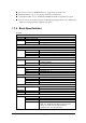
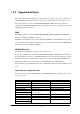
1.1.5 Model Name The following IT-2000s of MS-DOS version will be available. For price of each model, please consult with your local Casio representative.
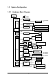
1.2 1.2.1 System Configuration Hardware Block Diagram CPU i486GX 1 Power switch For IT-2000W MASK ROM only FLASH ROM (DINOR) Battery voltage monitoring sensor DRAM Temperature sensor A/D converter UART/ SIR Illumination sensor COM 1 Buffer 8-pin Key RTC Keyboard controller Analog touch panel ASIC RTC IrDA 1.0 COM 2 16550 BUS Controller IrDA Driver/Receiver IrDA 1.
1.2.2 Supported Software The software used with this terminal can be divided into two categories: the system software that includes the BIOS, OS, and device drivers and the user software such as the development tools. The system software is stored on the DINOR FLASH ROM (1 MB), and the user software is supported from the SDK CD-ROM (version 4.0) supplied by Casio at free of charge. The following paragraphs describe the software. BIOS The BIOS program is stored in the DINOR FLASH ROM.
TFORMAT.EXE Basic drive (C:) F-ROM drive formatter Utilities For information about the utilities refer to Chapter 8 "Utility". File name Storage location SDK SDK SDK SDK Basic drive (C:) Basic drive (C:) SDK CAL.EXE CALC.EXE CLOCK.EXE CHKBATT.EXE XY.EXE FLINK.EXE LCDREV.EXE Description Calendar utility Calculator utility Clock utility Power status indication utility XY utility FLINK utility Reverse video utility Development Tool Libraries File name SLIBSYSD.LIB MLIBSYSD.LIB LLIBSYSD.LIB SYSLIB.
1.3 Precautions If reading the internal clock with INT21h the significant data should include and be limited to the seconds digits. On this terminal the time is read directly from the RTC so that the correct time can be attained at any moment, even during extended continuous use. As a result the 1/100 of a second digit is ignored. (refer to Chapter 6.3 “Clock Control Driver”) If it is necessary to reboot the system from an application, use the dedicated system library.
This system will not execute an alarm indication for an LB2 event (low sub-battery voltage) or LB3 event (low SRAM card battery voltage). Therefore, the application program side must acquire the alarm status via the system library and display an appropriate alarm message. If the volume of the buzzer is set to zero by the System Menu or system library, the LB1 (low main battery voltage) alarm will not be heard. Also, other sounds issued by the system will be inaudible.
Do not input “^P” from the DOS prompt. If it is input, “^P” requests DOS to redirect console output to printer. However, the IT-2000 does not have the printer being installed, it will enter into wait mode. For more information about the system library refer to Chapter 7.6.2 “System Library”. Also, refer to Chapter 2.2.4 “Battery Voltage Monitoring Process” for information about the low-battery voltage notification function.
2. Basic Software 2.1 Overview 2.1.1 Software Configuration The following diagram shows the software configuration of the IT-2000. Application Layer OBR Library System Library Keypad Library Application Int33h MS-DOS Layer PenMouse Driver System Driver APM BIOS Extended BIOS Keypad Driver Pen BIOS Hardware & BIOS Layer AT Architecture + Original Hardware Fig. 2.1 Note: The PenMouse driver and Keypad driver cannot co-exist on the system.
2.1.2 Memory Map The memory map of the IT-2000 is as follows. Extended Memory 100000h ROM BIOS NAND DISK BIOS/VGA BIOS Memory Mapped Disk I/F PC Card I/F EMS Windows 16 KB x 4 Reserved 0F0000h 0E0000h 0DC000h 0D8000h 0C8000h 0C0000h Video Buffer 128 KB 0A0000h System RAM 640 KB 000000h Fig. 2.
2.1.3 Drive Configuration The drive configuration differs for each model as described in the following: If F-ROM drive is supported RAM disk Drive A: [Read and Write] This drive is prepared for use after the RAM disk size is specified from the System Menu. The contents of this RAM disk will not be erased through a boot process or by pressing the RESET switch. Drive C: Basic drive (DINOR FLASH ROM) [Read Only] This drive starts up MS-DOS.
If F-ROM drive is not supported RAM disk Drive A: [Read and Write] This drive is readied for use after the RAM disk size is specified from the System Menu. The contents of this RAM disk will not be erased through a boot process or by pressing the RESET switch. Drive C: Basic drive (DINOR FLASH ROM) [Read Only] This drive is used to start MS-DOS. In this drive not only the main body of MS-DOS but also the maintenance programs such as the System Menu, etc., are stored. This is a read-only drive.
2.2 Basic System Operation 2.2.1 Overview Basic operation of this system on the terminal consists of the suspend/resume process and boot process operated by means of the Power switch and RESET switch, as shown in the following diagram. OFF STATE ON KEY ON STATE Application BOOT OFF Process RESET SWITCH OFF Process OFF EVENT System Menu BOOT OFF EVENT ON EVENT ON Process System Menu RESET SWITCH System Menu BOOT SUSPEND STATE ON KEY System Menu BOOT INITIAL STATE Fig. 2.
The following table summarizes the power-on processes provided for this terminal. System Menu boot process Application boot process Resume process Always executes CONFIG.SYS and AUTOEXEC.BAT located in drive (C:) for starting up the MS-DOS. Searches for CONFIG.SYS and AUTOEXEC.BAT prepared by the user and starts up MS-DOS from the drive where they are located. Restores the memory conditions that existed before the power was turned off and continues operating according to the conditions.
2.2.2 Power ON Process Overview The ON process is provided to make the system ready for use (ON state). The actual process varies depending on the settings at that point in time and the last OFF factor (the cause of the OFF action).
System Menu Boot Process Pressing the RESET switch sets the drive C: as the current drive, and MS-DOS is loaded from that drive. As a result, the System Menu that includes the maintenance program will be initiated (refer to “System Menu Boot Process” on this page). Resume Process This process restores the conditions that existed before the power was most recently turned off. Any application program that was running at that point in time can be continued.
Note: The RESET switch can be used not only for initiating the System Menu but also as the forced restart witch when the user application program under development hangs. However, note that if the RESET switch is pressed while the disk is being written to, the data may be corrupted. Therefore, the RESET switch should be pressed only while the power is off. Clock data or information on the RAM disk will not be lost if the RESET switch is pressed.
Auto Power ON function (only affects the resume process) activated by alarm The system power can be turned on (resumed) at the specified time by means of an alarm. However, this will not function if the next start-up method is set to the boot process in the system library. Auto Power ON function activated by the RING signal This function can be used if a modem is connected to the 14-pin expansion interface.
2.2.3 Power OFF Process Overview Turns off the system power. However, the power to all the devices is not turned off and some can be used for storing the information required for the next resume operation. This process is called the suspend process and the state of the system while off is called the suspend state.
OFF Factors The OFF factors refer to various causes that make the system enter the OFF state (suspend state), as follows: OFF factor Power switch Auto Power OFF (APO) Software Power OFF Power OFF due to time-out of low battery voltage (LB1) alarm If main battery voltage falls to an inoperable level (LB0) Power OFF due to RESET switch pressed Description System operation can be suspended by holding down the Power switch for more than a second.
Note: Hold down the Power switch for more than one second until the power is off. This is done to prevent the power from accidentally being turned off by the user. In addition, key input will not be enabled for approximately one second after the Power switch has been pressed. This occurs because the monitoring timer starts operating the moment the Power switch is pressed and does not allow key input for about one second until this timer expires. After this interval, key input becomes possible.
2.2.4 Battery Voltage Monitoring Process This terminal uses a main battery (lithium-ion battery pack) for driving the main unit, and a primary sub-battery (lithium battery) and a secondary sub-battery (lithium-vanadium battery) for backup. Application programs can acquire the status of these batteries through the APM BIOS or system library. Refer to Appendix C Acquisition of Suspend/Resume Event and Power Status.
Low Voltage Level The IT-2000 continuously monitors the voltage of the main battery, the primary sub-battery, and the SRAM card battery. This allows an application program to determine through the system library if the voltage of each battery reaches a warning level. The following table summarizes the low battery voltage warning levels, which application programs can acquire through the system library.
Main Battery Voltage Monitoring If the main battery voltage reaches LB1, the system issues a warning buzzer. If this warning buzzer sounds, either start recharging the battery or replace it with a fully charged battery as soon as possible. If one of these measures is not taken within ten minutes, the system will forcibly turn off the power for safety. The following diagram shows the main battery voltage against the time axis. Main Battery Voltage level to voltage Generate warning allow operation buzzer.
For information about the method used to replace the main battery refer to Chapter 2.2.6 “ How to Replace or Recharge Batteries”. Sub-battery Voltage Monitoring The sub-batteries are used for system backup while the main battery is being replaced. The subbatteries consists of two units: the primary sub-battery (button-type lithium battery) and secondary sub-battery (button-type lithium-vanadium battery). The secondary sub-battery is recharged by the voltage of the main battery.
Acquiring Power Status through Battery Status Acquisition Utility With the battery status acquisition utility the user can be advised of the current remaining voltage of the main battery, sub-battery status, or connector status in real time. For more information refer to Chapter 8.7 “Remaining Battery Voltage Display Utility”.
2.2.5 Low Consumption Current Process This terminal has (1) the APM BIOS installed to provide a low-power consumption capability. It works in combination with POWER.EXE from Microsoft Corporation. The low-power consumption capability is further enhanced by the use of unique power management functions, including (2) Auto Power OFF (APO) function, (3) Auto Backlight OFF (ABO) function, and (4) DOZE/RUN transition function.
Auto Power OFF Function (APO) This function automatically shifts the system to the OFF state (suspend state) if no event has taken place for a specified period of time from the touch panel, the keyboard, COM1, or a file. This time interval has been set to one minute by default. It can be modified using the System Menu or system library.
DOZE/RUN Transit Function On this terminal the system will reduce the clock speed of the built-in CPU if no activity (access to the touch panel, keys, COM1, or file) has occurred for a specified period of time (four seconds). The state in which the CPU clock speed has been reduced is called the "DOZE state" and the state in which the CPU is operating at full speed is called the "RUN state". If an activity occurs in the DOZE state, the system returns to the RUN state.
Note: If the power management function is disabled by the system library, the Auto Power OFF function (APO) is also disabled. This is because both the power management function and Auto Power OFF function use the same activity processing routine.
2.2.6 How to Replace or Recharge Batteries Replacement of Batteries The method used to replace the main battery, sub-battery, and SRAM card battery are explained here. Failure to observe the correct battery replacement procedure may result in a loss of data. Always observe the following steps in battery replacement. Main battery replacement Hold down the Power switch for more than one second to turn off the main unit power.
Note: The SRAM card is supplied power by the main battery when it is installed in the main unit. This means that the SRAM card can be used normally as long as it is in the slot, even if the voltage of the card battery is zero. In this case, however, the data on the SRAM card will be lost when the card is removed from the main unit slot. Since the Casio SRAM card is provided with two batteries, the data will not be lost for a short while even if one of them is removed.
2.3 Supported Devices 2.3.1 Display Unit Hardware Configuration LCD Resolution Tone Method VRAM RAM for hardware window FSTN semi-transparent liquid crystal display 192 x 384 dots B/W 16 gray scales (4 gray scales are identifiable) VGA compatible 512 KB 32 KB Note: With B/W liquid crystal displays the actual display colors will be changed to reverse video. About the Display Screen Since this terminal has a VGA controller, it can internally control the entire VGA (640 x 480 dots) screen.
Software Functions Standard Video BIOS is supported.
2.3.2 EL Backlight Overview This terminal has the following functions to control the backlight. For more information refer to Chapter 5, “Keyboard Controller”. Manual Backlight ON/OFF function Auto Backlight OFF function (ABO) Auto Backlight Control function (ABC) Manual Backlight ON/OFF Function The backlight can be turned on and off with the following methods. Press the 7 key after the Fn key to turn on or off the backlight. Call the system library to turn on or off the backlight.
2.3.3 Touch Panel Hardware Configuration Method Resolution : Analog type touch panel : 192 x 384 dots Software Function To enable application programs to acquire touch panel coordinates, the following two pieces of software are provided: PENMOUSE.COM With this PENMOUSE.COM application programs can acquire touch panel input through the mouse I/F. (refer to Chapter 6.5 “PenMouse Driver”.) KEYPAD.EXE With this keypad driver application programs can perform character input through the touch panel.
2.3.4 Disk Types of Disk Type RAM disk Basic drive F-ROM disk PC card Drive name A C D G or F Capacity 0 to 1920 Kbytes 768 Kbytes 0, 4, 8, 12, 16 or 24 Mbytes SRAM card, ATA card Note: The drive name of the PC card varies for each model. For more information refer to Chapter 2.1.3 “Drive Configuration”. RAM Disk Part of the main RAM can be assigned on the RAM disk using System Menu.
F-ROM Drive The F-ROM drive is supported as a disk for which both read and write operations are possible (only for models with the F-ROM drive). Various disk capacities are supported for each model: Disk capacity: 0 (models without F-ROM), 4M, 8M, 12M, 16M or 24 MB To format the F-ROM drive use the System Menu. For information about the formatting method refer to Chapter 3 “System Menu”. In this process the System Menu will call TFORMAT.EXE from drive (C:) to format the F-ROM drive.
2.3.5 Serial Communication Available Interfaces Port COM1 I/O Address 3F8h-3FFh COM2 2F8h-2FFh Name 8-pin serial I/F Uses Connection with a barcode reader or PC 14-pin serial I/F Connection with an expansion I/F device IrDA 1.0 COM3 3E8h-3EFh (Modem card) COM4 2E8h-2EFh IrDA 1.1 Communication with an I/O Box or between two IT2000s Modem card Communication with an I/O Box or between two IT2000s Remark Can be switched via the system library. If a modem card is used.
COM2 Either the 14-pin serial I/F or IrDA 1.0 can be assigned to this COM2 port depending on the system library setup. Both the 14-pin serial I/F and IrDA 1.0 can be used as a normal RS-232C interface. By default, the COM2 channel is not assigned to either device. Therefore, always use the system library to designate either the 14-pin serial I/F or IrDA, then turn on the power. The 14-pin serial I/F is located on the rear of the panel.
2.3.6 PC Card Hardware Overview Standard Register compatibility Slot Power supply Card lock switch Conforms to PCMCIA Release 2.1 Has register compatibility with Intel 82365SL Step 1 slot TYPE II Vcc : 5V (not operable at 3.3V) Has a card lock switch Recommended PC Cards Type SRAM card ATA Flash ROM card Model name DT-635MC (256 KB) DT-636MC (512 KB) DT-637MC ( 1 MB) DT-9031FMC ( 2.
Card Lock Switch The IT-2000 has a card lock switch to prevent accidental removal of the card. Any card can be made usable only after it has been inserted in the slot and the switch has been locked properly. However, since some types of cards do not allow this card lock switch to be closed, a library routine to disable this switch is supported. For more information refer to Chapter 7.6.2 "System Library”.
2.3.7 Clock Timer Clock BIOS 00h to 07h of the INT1Ah function are compatible with the IBM PC/AT. Since INT1Ah can be called in the C language, an alarm operation using the clock can be set with the system library. Alarm If an alarm operation is set using the INT1Ah or system library, it is possible to cause an INT4Ah interrupt at the specified time to issue the alarm.
2.3.8 Buzzer This terminal is provided with a buzzer function that is compatible, via an appropriate interface, with the IBM PC. The application side can sound this buzzer by controlling the I/O port assigned to 61h. It is also possible to modify the sound frequency by controlling channel 2 of the timer. For information about the method used to modify the frequency refer to the hardware manual of the PC/AT compatible machine.
2.3.9 Barcode Reader Overview The IT-2000 supports the following two Casio OBR (Optical Barcode Reader) models: DT-9650BCR ( Pen scanner ) DT-9656BCR ( CCD scanner) Connect the OBR to the COM1 (8-pin) port of this terminal, and set up the interface as follows. Synchronization Baud rate Data bit Parity bit Stop bit asynchronous 9600 bps 8 bits none 1 bit For communication between the OBR and this terminal use the OBR library.
2.3.10 Infrared Communication (IR) The infrared communication function of this terminal supports the protocol of IrDA 1.0 (see note below) and IrDA 1.1 standards. IrDA 1.0 can be used as the COM port for a general RS-232C. IrDA 1.1 can provide communication at a maximum rate of 4 Mbps by means of the dedicated utility (FLINK utility). IrDA 1.0 Item Synchronization Baud Rate COM Port Specification asynchronous 115.2 Kbps max. COM2 Remark Conforms to IrDA1.
2.3.11 Keys Hardware Overview Key configuration IRQ Key repeat function Simultaneous pressing of multiple keys Roll-over function 5 (column) x 3 (row) keys IRQ1 available not available not available Key Layout See the following key layout. Fn 7 8 9 - 4 5 6 CLR 0 1 2 3 Fig. 2.12 Fn key The "Fn" key should be used in combination with the numeric key. Hold down the "Fn" key and press a numeric key.
2.3.12 Sensors The IT-2000 has the following three types of built-in sensors: Illumination sensor Temperature sensor Battery voltage level sensor Attached to the upper section of this terminal and used to sense the ambient light intensity. It is used for the Auto Backlight Control (ABC) function. It cannot be controlled directly from the application. (For more information about the system library refer to Chapter 5 “Keyboard Controller”.
3. 3.1 System Menu Overview The system menu is a program and used to perform various setups (system clock, contrast of liquid crystal display, etc.) and implement (downloading) application programs, all of which are necessary to use this terminal. To start up the system menu press the reset switch located at the back of the main unit. When the reset switch is released a short beep will sound and, after a short while, a screen as shown in Fig. 3.1 will appear.
3.2 Basic Operation In the system menu a common set of key operations are used. The following list shows the keys that can be used in the system menu. Current Condition Line cursor is on Key Operation 8 2 CLR RET Others 0 to 9 RET CLR Operation Process Moves the line selection cursor up one line. Moves the line selection cursor down one line. Moves the line selection cursor to the upper menu area, if it is located in the lower menu area. Confirms and executes the currently selected menu item.
3.4 Key Click Sound Setup Function Sets the key click sound ON and OFF. If it is set to ON, a key click sound is heard when a key is pressed or when the keypad is touched. It does not sound if it is set to OFF. Fig. 3.3 Operation Select ON/OFF with the “ 0” or “ 1 “ key, then confirm the selection with the “RET” key. Key Operation 0 key 1 key . (decimal) key RET key CLR key Others Function Sets the key click sound to OFF. Sets the key click sound to ON. Toggles to ON and OFF of the key click sound.
3.5 Buzzer Volume Setup Function Sets the volume of the buzzer (beep). One of the four levels (OFF/Small/Medium/Large) can be selected. Fig. 3.4 Operation Make a selection with a key, “ 0” to “ 3 “, and confirm the selection with the “ RET” key. Key Operation 0 to 3 keys . (decimal) key RET key CLR key Others Function Selects the corresponding number. Toggles between two selections. Confirms the currently selected setup and exits this operation.
3.6 Contrast Adjustment Function Adjusts the contrast of the liquid crystal display. Fig. 3.5 Operation Press the “8 “ key to increase the contrast or press the “ 2” key to decrease the contrast. Press the “ RET” key to confirm the setting. Key Operation 8 key 2 key RET key CLR key Others Function Increase the contrast. Decrease the contrast. Confirms the currently selected contrast setup and exits this operation. Cancels the currently selected contrast setup. Invalid.
3.7 Auto Backlight Setup Function Sets the auto backlight control ON or OFF (refer to Chapter 5 “Keyboard Controller"). Fig. 3.6 Operation Select ON/OFF with the “ 0” or “ 1” key, then confirm the selection with the “RET” key. Key Operation 0 key 1 key . (decimal) key RET key CLR key Others Function Turns the auto backlight control to OFF. Sets the auto backlight control to ON. Toggles to ON and OFF of the auto backlight control. Confirms the current setup and exits this operation.
3.8 Auto Power OFF Setup Function Sets the time-out period of the auto power off function (APO) (refer to Chapter 2.2.3 “Power OFF Process"). This time-out period is the interval between when no key entry or no entry on the touch panel is made and when the power of system is shut off automatically. Fig.3.7 Operation Set the APO time out period with the “ 2” or “ 8 “ key, then confirms the setting with the “ RET” key.
3.9 Touch Panel Calibration Function Adjusts the calibration of touch panel. If an inconsistency is noted between the target position and the position actually touched on the touch panel, correct it by performing this calibration adjustment. Fig. 3.8 Operation Adjustment of the calibration : When the buzzer sounds, release the stylus from the touch panel.
Note: If an mark does not disappear and the arrow does not move to the next position even if the mark has been touched by the stylus, an incorrect position was likely touched. Touch the correct position. Key Operation 1 key 2 key Others Function Adjusts the touch panel calibration starting from the beginning. Returns to the menu screen.
3.10 YMODEM Utility Function Used to achieve a file transfer via the COM cable. Communication can be established either between an AT-compatible machine (PC) and an IT-2000 (main unit), referred to as "PC-to-HT communication". A dedicated 9-pin DSUB-8-pin cross-type cable (DT-9689AX) is required to connect both the terminals. This utility does not have functions to allow communication between HT and HT. Use the FLINK function for the HT-to-HT communication. Fig. 3.9 Fig. 3.10 Fig. 3.
Note: When the cable comes off while the communication takes place: If the connection cable is accidentally unplugged while communication between the IT-2000 and PC is taking place, a communication error results and communication is interrupted. In this case the communication software on the PC will display an error message and interrupt transmission/reception, however, some data may remain in the transmission buffer.
Operations (1) SEND FILE TO HT (one file transmission from IT-2000 to IT-2000) This function may be available in future (as of now, not available). It is not allowed to use the function. If the file transmission between IT-2000s is needed, FLINK utility may be used (refer to Chapter 3.11 “FLINK Command”.). (2) SEND FILE TO PC (one file transmission from IT-2000 to PC) This function is used to copy an optional file from an IT-2000 to PC. To do this, use commercial terminal emulation software on the PC side.
When the "Normal End" message is displayed on the IT-2000 side, file reception has been completed. For information about the copy destination directory refer to the following table. If the “CLR” key is pressed during communication, file reception will be interrupted. It will take about 10 seconds for communication to completely stop. The destination drive/directory will vary depending on whether the destination side has an FROM drive (D:) and/or RAM disk (A:).
3.11 FLINK Command Function Files can be transferred by infrared communication (IR). This can be implemented either as PC-toHT (AT-compatible machine to IT-2000) communication or as HT-to-HT (between two IT-2000 terminals) communication. To perform PC-to-HT communication an I/O Box and a PC-side communication utility "LMDOS.EXE (for DOS)" is required. Fig. 3.13 Fig. 3.12 Fig.3.
Note: If the identical file name exists on the reception side, this command overwrites the existing file. At this time, the system does not unconditionally overwrite the existing file but creates a temporary file on the reception-side disk and attempts the overwrite after file transmission has been competed. This protects file data even if transmission of the file fails.
Note: If the “CLR” key is pressed during file transfer, transfer will be interrupted. It will take about 10 seconds for communication to completely stop. REMOTE SERVER (remote server mode ) The remote server mode is used by the system which assigns the right of issuing a transmission request to the partner side and enters the wait state for a request from the partner. To facilitate communication between two IT-2000 terminals, set the reception side to this mode.
3.12 System Date/Time Setup Function This is used to set (modify) the date and time of the built-in timer in the IT-2000 unit. Fig. 3.15 Operation Enter in the following order: year -> month -> day -> hour -> minute. Press a numeric key and the corresponding number will appear in the cursor position. Press the “ RET” key to advance to the next setting. If the “RET” key is pressed without making a numeric entry, the cursor will advance to the next setting without affecting the previous value.
3.13 Command Prompt Function This is the MS DOS command prompt screen. An appropriate DOS command can be inputted through the keypad. This DOS command prompt is the result of calling COMMAND.COM as a child process from the system menu. Consequently, if the EXIT command is entered, operation returns to the system menu. Fig. 3.
3.14 RAM Disk Size Change Function This screen is used to set the RAM DISK size (capacity). The setting will become valid after the system has rebooted. Fig. 3.17 Operation Setting up the RAM disk Adjust the RAM disk size with the “8” and “2” keys. Confirm the setup with the “ RET” key. When the "Hit Any Key... " message is displayed, press any key other than the “Fn” key. The IT-2000 is turned off. After making sure that it turns off, press the reset switch to turn on the main unit again.
1 key 0 key Others Formats the RAM disk (Format confirmation screen). Aborts formatting of the RAM disk. Invalid. Operations with the touch panel are not permitted.
3.15 Disk Format Function Formats the RAM disk or user drive. Fig. 3.18 Operation In the screen shown above, use the “2” or “8” key to select whether the RAM disk or user drive is to be formatted, then press the “RET” key. This makes the following screen appear. In this screen press the “1” key to move the cursor onto "YES" and press the “RET” key to start formatting.
Key Operation 2 or 8 key 0 key 1 key . (decimal) key RET key CLR key Others Function Selects the objective item (drive selection screen). Does not perform formatting (formatting start screen). Starts formatting (formatting start screen). Toggles YES and NO options of formatting. Confirms the current setting. Cancels the current setting. Invalid.
3.16 System Initialization Function Sets all the system setups to their defaults. Fig. 3.21 Operation The following table shows the available key operations. Key Operation 0 key 1 key . (decimal) key RET key CLR key Others Function Does not initialize the system. Initializes the system. Toggles YES and NO options of initialization. Confirms the current setting. Cancels the current setting and exits this operation. Invalid.
3.17 Password Entry Function When "FILE TRANSFER" or "MAINTENANCE" is selected for the first time after the system menu is initiated, the operator is requested to enter a password. Fig. 3.22 Operation With the keypad enter "system" (lowercase letter), then press the “RET” key. If the “CLR” key is pressed without entering a character, the password entry operation will be canceled.
4. MS-DOS 4.1 Overview If a personal computer is booted-up with a floppy disk in the drive, first an attempt will be made to read MS-DOS from the floppy disk, and if a copy of MS-DOS does not reside on the floppy it is loaded from the hard disk (C:). However, this method cannot be used on this terminal since its basic drive (C:), which corresponds to the hard disk of a PC, is defined as a read-only device.
As described above, if the system power is turned on without an application installed (i.e. the conditions just after purchase), the CONFIG.SYS and AUTOEXEC.BAT files locating on the basic drive will be executed automatically. This inevitably initiates the System Menu (maintenance program). Therefore, if not only CONFIG.SYS and AUTOEXEC.BAT, but also an application program are installed on the user drive, it is possible for the application program to be automatically initiated from the user drive.
4.2 How to Write CONFIG.SYS and AUTOEXEC.BAT This section explains how to write the CONFIG.SYS and AUTOEXEC.BAT files mentioned in the previous section. A basic explanation of the CONFIG.SYS and AUTOEXEC.BAT is not given here. For further information about these files refer to the MS-DOS manual or appropriate technical documents. Observe the following points if writing a CONFIG.SYS file. The System Driver (SYSDRV.SYS) is required to operate this terminal.
Note: 1 DOS=HIGH,NOUMB This specifies that the main part of DOS is to be loaded in the HMA and, consequently, the UMB (Upper Memory Block) is not used. This terminal does not support a memory space for UMB if the EMS memory is to be used. Therefore, always specify NOUMB when using the EMS. 2 DEVICE=C: SYSDRV.SYS This driver is required to operate this terminal. Always install it before all other drivers. 3 DEVICE=C: HIMEM.SYS /M:2 Never fail to specify the "/M:2" option. 4 POWER.
Example of AUTOEXEC.BAT The following example shows a typical AUTOEXEC.BAT script. Since this example assumes that the system is booted from either the RAM disk or the NAND F-ROM drive, it is necessary to partially modify it if booting up from the ATA card. For information about booting from the ATA card refer to Chapter 4.3, "Card Boot". 1: C: ENDATA 2: C: CASIOAPM 3: (Environment variables setup and application call, etc.
4.3 Card Boot Basically the "card boot" operation boots MS-DOS from the ATA card, just like it is booted from a floppy disk. For this terminal the boot operation looks the same as this case. However, this terminal uses a boot process greatly different from a general card boot so that the MS-DOS in the drive C is always loaded, in such a way that MS-DOS not residing in the card is booted. Usually, in order to access the ATA card, a specific card driver is required.
the drive G, which is currently enabled, will be disabled. This problem arises from the fact that the hardware conditions established by initialization with CARDID.EXE are lost since access to the drive F was executed by means of specific codes included in the BIOS. To avoid this problem, these specific codes in BIOS should be disabled. ENDATA.COM is used to do this. If ENDATA.
CONFIG.SYS which resides on the drive C. However, CARDID.EXE cannot be registered as a device driver at a card boot. If this CARDID.EXE is registered as a device driver, two drives may be enabled concurrently if MS-DOS executes CONFIG.SYS. In addition, if ENDATA.COM is called with the INSTALL command, the drive G is enabled exclusively.
5. 5.1 Keyboard Controller Overview This terminal is equipped with a sub-CPU dedicated to controlling the keyboard, touch panel, backlight, and various sensors. This chapter describes major tasks assigned to this sub-CPU. LCD Brightness El Backlight Temperature Sensor Main CPU Command Sub-CPU Illumination Sensor Data Battery Voltage Sensor Buzzer Volume Touch Panel Fig. 5.
5.2 Keyboard Control The keyboard control of this terminal is compatible with the IBM PC/AT. The keyboard controller senses if a key has been pressed and sends a MAKE or BREAK code to the main CPU. Application Program Primary/Secondary Code Function Process BIOS Hardware Interrupt Process Keyboard Input Buffer System Scanning Code Sub-CPU Keyboard Fig. 5.
Secondary code Basically a system scan code is assigned to each key, however, for some keys, different codes will be assigned depending on the Fn key. Code Table The following diagram shows the relationship between the keyboard keys and primary codes. Fn 7 8 9 - 4 5 6 CLR 0 1 2 3 37 38 39 2D 2E 34 35 36 1B 30 31 32 33 0D Fn key not pressed 003E 003F 0040 0044 003B 003C 003D Fn key pressed Fig. 5.
5.3 Touch Panel Control Function The keyboard controller has incorporated a program for acquiring the touch coordinates of the touch panel. This program compensates these acquired coordinates with the values obtained through calibration so that correct coordinate values can be calculated. The calculated coordinates will be passed to a ROM-resident program called PEN BIOS when mouse interrupt occurs.
5.4 Sensor Control This terminal has the following three types of sensors installed to serve as dedicated devices for handy terminal. Sensor type Temperature sensor Illumination sensor Remaining battery voltage sensor Purpose of Use Detects the temperature inside the main unit. This result will be used to automatically compensate the LCD brightness. Detects the ambient light intensity to automatically turn on and off the backlight.
5.5 Backlight Control This terminal has incorporated two types of automatic backlight control functions: ABO (Auto Backlight OFF) and ABC (Auto Backlight Control). The ABO function is used to turn off the backlight if no key or touch panel input has been made for a given period of time, and the ABC function is used to automatically turn on and off the backlight depending on the intensity of the ambient light. These operations are performed by the keyboard controller.
Transition of Backlight Control Methods The concept of ABC lies in automating user operations. However, automatic control depends on the illumination sensor. It cannot be perfect because various types of light, sunlight or room light for example, may be incident to the sensor. Consequently, this requires manual ON/OFF control even if under ABC control. This leads to a further problem wherein the user may forget to turn it on or off.
ABC disabled Backlight ON state ABC disabled Backlight OFF state ABC enabled Backlight ON state ABC enabled Backlight OFF state ABC temporarily disabled Backlight ON state ABC temporarily disabled Backlight OFF state 1 2 3 4 5 6 Press F7 key 2 1 ABO time-up 2 ABC Enable 3 or 4 ABC Disable --- Becomes dark Ignore Becomes light Ignore Ignore Ignore *1 3 or 4 --- *1 --- 6 Ignore Ignore 2 --- 4 5 --- Ignore 2 3 --- 4 3 Ignore 2 3 --- 3 *3 --- Ignor
6. 6.1 Drivers Overview The following drivers are supplied for this terminal. Install them as required for operation. Name System driver File name SYSDRV.SYS Purpose Driver required to operate the system. This driver must be installed. Clock control driver TIME.SYS Hardware window manager Keypad driver HWWMAN.EXE PenMouse driver PENMOUSE.COM Executes the process that restores the clock condition at a resume-boot in cooperation with POWER.EXE. This driver must be installed.
6.2 System Driver 6.2.1 Function The system driver (SYSDRV.SYS) must be installed because it executes critical processes in this terminal. The system driver mainly performs the following processes. LB1 monitoring and warning Monitors the main battery conditions and sounds a warning buzzer if an LB1 event is detected. It also forcibly turns off the system, if the battery voltage has not recovered within ten minutes of the buzzer sounding.
6.3 Clock Control Driver 6.3.1 Function This driver adjusts the system time on this terminal. This driver must be installed. On a general PC a timer interrupt occurs every 55 msec to update the clock tick counter, which is one of the BIOS system variables, and the clock overflow counter. The clock tick counter is incremented each time the timer interrupt occurs and read out from the real-time clock (RTC) when the PC power is turned on, and disappears when the power is off.
6.3.2 Startup Method This driver is loaded by defining the DEVICE statement in the CONFIG.SYS file. TIME.SYS is stored in the basic drive (C:). Format DEVICE=C: TIME.SYS Start option None Note: TIME.SYS must be loaded immediately after POWER.EXE.
6.4 Keypad Driver/Hardware Window Manager 6.4.1 Function The keypad driver (KEYPAD.EXE) is used to add the keypad function to the system. Application programs can use the keypad by calling the keypad driver functions via the keypad library (refer to Chapter 7.6.3 “Keypad Library”). This keypad driver internally calls the hardware window manager that enables the use of the hardware window. Therefore, the use of the keypad driver requires the residence of the hardware window manager.
6.4.2 Startup Method Format HWWMAN [Option] KEYPAD [Option] Start option /R Cancels the residence. To make each driver resident in the main memory, make the following specification at the DOS prompt. Always install the hardware window manager first. These drivers are stored in the basic drive (C:). >HWWMAN C: >KEYPAD C: The residency of these drivers can be released by specifying as follow. The keypad driver must be released first.
6.5 PenMouse Driver 6.5.1 Overview The PenMouse driver (PENMOUSE.DRV) simulates the operation of the mouse driver (INT33h) specific to the personal computer using inputs received from the touch panel. The PenMouse driver makes it possible to run on the IT-2000 terminal an application that was designed for use with a mouse driver on the personal computer. However, perfect simulation cannot be achieved because of the physical difference between the mouse and touch panel.
6.5.2 Startup Method The PenMouse driver is supplied as an SDK. Before use, copy it to the F-ROM drive (D:) or RAM disk (A:). To load the PenMouse driver, make the following specification at the DOS prompt. Format: PENMOUSE [Option] Start option: /R 6.5.3 Cancels the residence.
The functions supported by this driver are summarized below. Function Initialize Description Returns information as to whether the mouse can be used and sets the mouse function to the initial conditions. To start using the mouse this function must be called.
Set Cursor Position Places the cursor at the specified position Input: AX = 4 CX = X coordinate of the cursor position DX = Y coordinate of the cursor position Output: None Read Pushed Counter and Position Reads the number of times the specified mouse button is pressed, the cursor position when the specified button was last pressed, and the current button status. If this function is called, the number of times pressed is initialized to 0.
Set X Range Determines the range of cursor movement on the screen (maximum and minimum in the X direction). Input: AX = 7 CX = X coordinate of the left limit of cursor movement DX = X coordinate of the right limit of cursor movement Output: None Set Y Range Determines the range of cursor movement on the screen (maximum and minimum in the Y direction). On this terminal, if the user makes a touch outside the range set by this function, the limit value is acquired.
Set User Handler Sets up the interrupt condition required to call the corresponding subroutine in the application program as well as the subroutine to be called. If an interrupt occurs, the following values are stored in the register. Input: AX = 12 CX = Interrupt mask b0=1 Cursor position is modified. b1=1 Left button is pressed. b2=1 Left button is released. b3=1 Right button is pressed. b4=1 Right button is released.
Set Mouse Resolution (Dummy Function) Sets up the factor by which cursor movement on the screen reflects actual mouse displacement. This is a dummy function. Input: AX = 15 Output: None Set Erase Cursor Range (Dummy Function) Sets up the range within which the cursor is off the screen. This is a dummy function. Input: AX = 16 Output: None Replace User Handler Sets up the interrupt condition required to call the corresponding subroutine in the application program as well as the subroutine to be called.
Restore Mouse Information (Dummy Function) Restores the mouse driver conditions that have been saved by "Get Mouse Information". This is a dummy function. Input: AX = 23 Output: None Set Interrupt Subroutine (Dummy Function) Sets up the interrupt condition required to call the corresponding subroutine in the application program as well as the subroutine to be called. This function is the same as "Set User Handler" (AX=12), except that a set of key strokes can be included in the interrupt mask.
Get CRT Page Number (Dummy Function) Acquires the CRT page number in which to display the cursor. This is a dummy function. Input: AX = 30 Output: None Disable Mouse Driver (Dummy Function) Restores all the interrupt vectors used by the mouse driver, except INT31h, to the values they had before the mouse driver was installed. This is a dummy function. Input: AX = 31 Output: None Enable Mouse Driver (Dummy Function) Again sets up the values of all interrupt vectors used by the mouse driver.
7. 7.1 Application Development Overview This terminal uses the IBM PC/AT architecture. The actual display size is 192 (H) x 384 (V) pixels, internally with the area of 640 (H) x 480 (V) pixels, is supported. Therefore, if the user develops an application that makes use of the upper left 192 (H) x 384 (V) region of the display, a dedicated application program will run on this terminal.
7.2 Notes on Developing Application Any program that uses the COM port must turn on the power to it in advance using the system library. The power to the COM port remains on once it has been turned on, or until it is turned off by the system library or until the RESET button is pressed. Therefore, do not forget to turn off the power to the COM port when it is no longer required. This power is automatically turned off during the suspend state, but power is restored to it if system operation is resumed.
7.3 Development Environment 7.3.1 Development Environment To develop application programs a 16-bit compiler, Microsoft C/C ++ 7.0 or later, and a computer on which the compiler can run are required. 7.3.2 Application Development Library For this terminal various libraries such as the keypad library and OBR library, which is used to enhance the efficiency of developing applications.
7.3.3 Simulation Driver As explained above, the libraries for this terminal only control hardware that is compatible with the IBM PC/AT. This is important to remember if application programs for the terminal are developed on a personal computer. Although each library is linked to the application program to form an executable program, they do not contain code that is specific to the hardware of the handy terminal.
7.4 Program Development Procedure The following diagram shows the basic procedural flow used to develop an application program that runs on this terminal. The following paragraphs explain the details of each phase of the procedural flow. Start Transfer Creation/Edition of sourcecode Operation check on IT-2000 Compile/Assemble Link End PC simulation NG Operation OK OK < PC side > Fig. 7.
7.4.1 Creation of Execution File Application developers should develop programs using MS-DOS, IBM PC/AT BIOS and various application development libraries. The following sample program is used to turn on and off the backlight. With this program the backlight will be turned on or off if either "1" or "0", respectively, is entered through the numeric keypad. This program can be terminated by the input of the ESC key. #include #include "syslib.
Next, create the execution file with the following procedure. C: SAMPLE>cl -c -Zip -Otin -Ic: IT-2000 include test.c Microsoft (R) C/C++ Optimizing Compiler Version 8.03 Copyright (c) Microsoft Corp 1984-1995. All rights reserved. test.c C: SAMPLE>link /LI /m test,,,c:IT-2000 lib slibsysd; Microsoft ( R ) Segmented Executable Linker Version 5.63.2 20 Nov 29 1994 Copyright (C) Microsoft Corp 1984-1995. All rights reserved. C: SAMPLE> IT-2000.
7.4.2 Debugging Through Simulation An application is debugged using the simulation driver. The configuration of simulation drivers to be loaded varies depending on the application program to be developed. Library or device to be used 1 2 System library Keypad library 3 Touch panel (PENMOUSE.COM) At operation on IT-2000 SYSDRV.SYS SYSDRV.SYS HWWMANP.EXE KEYPADP.EXE PENMOUSE.COM When simulator is active SYSDRVP.COM SYSDRVP.COM MOUSE.COM HWWMANP.COM KEYPADP.COM MOUSE.
The following shows the result after the system driver was installed as the resident simulation driver and the sample program was executed. Fig. 7.4 Under this condition the program simply waits for key input. The backlight is off. To confirm this condition use the monitor function of the simulator. Under the default condition and if the F9 key is pressed, the internal status of the simulator is displayed on the far right of the screen, as shown below.
course be performed using Microsoft's CodeView debugger. For more information about each simulation driver refer to Chapter 7.5 "Simulation Driver". 7.4.3 Operation Check on IT-2000 (Using COM2KEY/XY) If software coordination through simulation has been completed, it should be transferred onto the IT-2000 for operation checks. To do this use the COM2KEY utility.
Use the debugger as required. DEBUG.COM, which is the standard MS-DOS debugger, is stored on the backup CD-ROM. If it is transferred onto the user disk by the above mentioned procedure and initiated according to the following procedure, remote debugging is made possible on the terminal software of the personal computer. D:>debug aplic.exe -r AX=0000 BX=0000 CX=27C7 DS=2DEF ES=2DEF SS=30BC 2DFF:0420 B430 7.4.
How to create a card for installation : Make an appropriate directory on the ATA card and copy the application program, files that are used by this application program, CONFIG.SYS, and AUTOEXEC.BAT onto this directory. Create CONFIG.SYS and AUTOEXEC.BAT for card boot. At the end of AUTOEXEC.BAT add a line for copying the above mentioned directory wholly onto the user disk. The above steps complete the creation of a card for installation.
7.5 Simulation Driver The simulation driver is used to develop on a personal computer the application programs that run on the IT-2000. The application development libraries supported for this terminal control only the hardware that is compatible with the IBM PC/AT. This is important to remember if the application programs for the terminal are developed on a personal computer.
7.5.1 System Driver Simulator (SYSDRVP.COM) Overview This simulation driver simulates the operation of the system driver on the personal computer. It also contains the run units of various functions supported by the system library. File name SYSDRVP.COM Function Under the default condition and if the F9 key is pressed, the internal status of the simulator is displayed at the far right of the screen.
Startup Method This utility is included in the SDK. Since this is a memory-resident type COM execution file, it should only be used if it resides in memory. Startup Option Format: SYSDRVP [Options] Options /R /H1=code Releases residence, if it is currently resident. Specifies a hot key which displays internal status. Code of the hot key can be specified by a value in hexadecimal number which is returned with INT16 (AH=10h).
7.5.2 Hardware Window Manager Simulator (HWWMANP.COM) Overview This simulator simulates only the display functions of the keypad driver on a PC. It cannot function by itself. For information about the display functions of the keypad driver see below. File name HWWMANP.COM Startup Method This utility is included in the SDK. Since this is a memory-resident type COM execution file, it should only be used if it resides in memory.
7.5.3 Keypad Driver Simulator (KEYPADP.COM) Overview This simulator will simulate the keypad driver and keypad library on a PC. File name KEYPADP.COM Function Key input Coordinate input Keypad display Keycode input Simulates on PC keyboard input and keypad input on the screen using the keypad library. Simulates on a PC coordinate input from the mouse using the keypad library. Simulates the keypad driver on PC Supports input of 2-byte hexadecimal codes.
Termination Codes and Messages Termination code Message 00 NORMAL END 01 ABNORMAL END Description Normal termination SYSDRVP or HWWMANP is not installed. EMS memory driver was not enabled. KEYPAD.DAT not found. Parameter error About the Key Input If this simulator is resident in memory, input through the keypad is permitted by clicking in the region that corresponds to each key, in addition to key input via the PC keyboard.
Displaying Simulated Keypad If this utility is initiated with the G/ option, a simulated keypad will be drawn in the position specified by the X coordinate provided that the video mode of the VGA BIOS (INT10h) is set to 12h (16-color graphic mode of 640 x 480 dots). Fig. 7.10 Since this display position in the X direction can be modified with the /G option at the start of the resident utility, it is also possible to display the simulated keypad so it will not be overwritten by other displays. Fig. 7.
About Hexadecimal Code Input Even if the keypad is active, key input using the mouse is disabled for the simulator on the PC if the /G option is not specified. To avoid this conflict, it is possible to enter a hexadecimal code with the menu accessed from the F10 key where the keypad is active. Enter 2 bytes of normal keycode for each hexadecimal code.
7.6 Library 7.6.1 Overview Since the IBM PC/AT architecture has been adopted in this system, all libraries including graphic library supported by Microsoft C/C++ ver. 7.0 or later versions can be used. In addition to those, the following dedicated libraries are available for the IT-2000 system. Name of library System Library Keypad Library OBR Library Description Dedicated libraries for IT-2000 and to control various devices available to the system.
7.6.2 System Library Overview The IT-2000 has various types of devices that can be controlled by the HT-generic software which is built upon the base of PC/AT architecture. This library is used to control these dedicated devices from application programs developed with the C language. Since this library provides lower-level programs concerning the hardware and system operations, exercise great care if integrating them into your programs.
List of Libraries The following functions are supplied in the system library: Function Acquisition of BIOS Version Acquisition of Memory Device Size Setting/Acquisition LCD Contrast Increasing/Decreasing LCD Contrast Switching Over COM2 Channel Setting/Acquisition Reason Mask for Reboot Reboot Request Page 132 133 133 134 135 136 Function Software Card Lock Acquisition of Connector Status Key Click Sound ON/OFF Acquisition of Key Click Sound Status Acquisition of Reboot Reason Acquisition of OFF Reason P
Acquisition of Memory Device Size If the memory device size is designated, the total capacity of the DRAM and the number of NAND FROM chips is read. The memory device size is the total capacity of all the physically installed devices, and not the disc capacity.
SYNTAX int SYS_SetLcdContrast(int nValue); INPUT nValue = Correction value to be set OUTPUT =0 Normal = -2 No response from KBC. = -3 VxD not registered (for IT-2000W only) Note: “WINFAR” will be treated as a far pointer only on IT-2000W models. Increasing/Decreasing LCD Contrast The contrast of the LCD display varies with the ambient temperature. Therefore, this terminal automatically detects the ambient temperature and determines an optimal contrast based on the acquired data.
Switching Over COM2 Channel IR, 14-pin, or 3-pin communication interface can be selected on the COM2 port. However, since the 3-pin interface is an optional means to maintain software compatibility with other models, it is not implemented on this terminal.
Setting/Acquisition of Reason Mask for Reboot To acquire the reboot request reason, enable or disable “mounting on I/O Box” or use of the CI signal for boot-up.
Setting ABO Time The ABO (Auto Backlight OFF) function is used to automatically turn off the backlight if neither key entry nor touch-panel entry is permitted for a certain period of time. This function is used to set the ABO time. Enable ABO by selecting a number between 1 and 15, which corresponds to a period of between 20 seconds and 5 minutes. SYNTAX int SYS_SetAboTime(int nValue); INPUT nValue = ABO time 0 Not activate ABO 1 to 15 Activates ABO in specified number x 20 seconds.
Setting ABC (Auto Backlight Control) Status The ABC (Auto Backlight Control) function is used to sense the ambient light intensity and automatically turns ON/OFF the backlight. This function is used to enable or disable the ABC function.
Setting/Acquisition of ABC Threshold The ABC (Auto Backlight Control) function is used to sense the ambient light intensity and automatically turns ON/OFF the backlight. This function is used to set marginal levels across which the backlight changes from ON to OFF or from OFF to ON. If the readout on the AD converter falls below OnValue, the backlight turns on, and if it exceeds OffValue, the backlight turns off. If these two levels are identical or too close each other, the backlight may flicker.
Backlight ON/OFF This function is used to forcibly turn ON or OFF the backlight. If turned ON by this function, the backlight will remain on until Backlight OFF is triggered by the Backlight OFF function or ABO. If this function is activated under the ABC control, the ABC will be temporarily disabled, and will be enabled again when Backlight OFF is triggered by the Backlight OFF function or ABO.
Setting Buzzer Volume Sets the buzzer volume to one of four levels: Large/Medium/Small/OFF. SYNTAX int SYS_SetBuzzerVolume(int nVolume); INPUT nVolume = 0 OFF 1 Small 2 Medium 3 Large OUTPUT = 0 = -1 Normal Parameter error = -2 No response from KBC = -3 VxD not registered (for IT-2000W only) Acquisition of Buzzer Volume Acquires the buzzer volume as one of four levels: Large/Medium/Small/OFF.
Acquisition of Device Power Status Acquires the current power conditions (ON/OFF) of each device. SYNTAX int SYS_GetDevicePower(int Device); INPUT Device = device to be selected 2 IrDA 3 14-pin I/F 5 8-pin I/F Other Reserved OUTPUT 1 Power ON 0 Power OFF Note: This function is used to control the power to devices of this system. Never designate parameters other than those specified on this page. Device Power ON/OFF Used to turn ON and OFF the power of each device.
Software Card Lock Sets or acquires the Lock/Unlock status of the software-type card lock switch. This machine has a card lock mechanism that is on the card case to prevent accidental removal of the card. This mechanism has a software driver that detects the released state of this lock and executes the appropriate file closing procedure. However, some types of cards, depending on the card shape, can not be fastened by the lock switch. If this is the case, even if a card is present it will not be detected.
Acquisition of Connector Status Acquires the connection setting of the I/O Box and AC adaptor. SYNTAX int SYS_GetConnectorStatus(int nType); INPUT nType = Connector type 0 I/O Box 1 AC adaptor or I/O Box OUTPUT = 0 Normal termination = 1 Connected = -1 Parameter error Key Click Sound ON/OFF Sets the key click sound to ON or OFF.
Acquisition of Reboot Reason Used to acquire the reason the system was rebooted. SYNTAX int SYS_GetPowerOnFactor(); INPUT None OUTPUT b0 Power key b1 Reset button b2 Alarm b3 Ring signal b4 IT-2000 is being set on I/O Box Note : If the reset button is pressed the system menu is initiated. This means that an application program will never acquire the status of "Reset switch being pressed" as the reboot reason. Acquisition of Reason for OFF Acquires the reason that the system was most recently turned OFF.
Setting Cancellation of Next Resume Process Sets the power-on process (Resume/Boot) for each power OFF reason. The default setting is Resume On.
Request of Suspend (Software-triggered OFF) Used to turn off the system with the software. If there is a need to specify the next boot-up process, complete "Setting Cancellation of Next Resume Process" beforehand, then call this function. SYNTAX void SYS_PowerOff(); INPUT None OUTPUT None Acquisition of Low Battery Voltage Status An APM (Advanced Power Management) BIOS has been installed in this terminal.
OUTPUT = 0 = -1 Normal Parameter error Note : Auto Power OFF will work if the power control function is active. For more information about the power control function refer to "Setting/Acquisition of Status of Power Control Function". Acquisition of APO Time Acquires the currently set APO time. SYNTAX int SYS_GetApoTime(); INPUT None OUTPUT 0 Disable the APO. 1 to 15 Enable the APO in the specified-number of minutes plus 30 seconds. The actual APO time has an error of +/- 25 seconds.
SYNTAX int SYS_SetAlarm(int hour, int min, int sec); INPUT hour = hours (in decimal number) min = minutes (in decimal number) sec = seconds (in decimal number) OUTPUT 0 Normal < 0 Error (error within INT1Ah) Note: This function simply calls INT1AH (AH = 6) internally. Therefore, if this function or INT1Ah (AH=6) is called and if the alarm has already been set, an error results. Note that the validity of parameters as time is not checked.
Resetting Alarm This function prohibits an INT4Ah interrupt by internally calling INT1Ah (Ah = 7). Note that neither the time data set for the RTC is erased nor is the power ON alarm setting for the SYS_SetPowerOnAlarm() function canceled by this function. If this function is called with the power ON alarm active, the alarm is temporarily reset. However, the RTC will be automatically set to active after the power is turned off again to enable the power ON alarm.
Note : The power ON alarm set with this function will be reset if rebooting occurs because the reset button is pressed or due to the software. Setting/Acquisition of Status of Power Control Function This terminal has incorporated unique power control functions: the auto power OFF mode and DOZE mode (CPU low-speed operation mode).
Setting Key Click Sound ON This function is used by application program to turn ON the key click sound. An example of the use is, when an button image on the LCD screen is touched it turns ON the sound. The sound is the same tone as those when ten key and keypad are pressed. The setting of key click sound ON/OFF controls this sound (refer to “Key Click Sound ON/OFF” on page 144.).
7.6.3 Keypad Library Overview This library is used to make an entry through the keypad or acquire the coordinates on the screen being touched. Note about the Libraries The key input library is supplied on one of the four models suitable for the application program developed by the user. Any application program that uses the key input library should include keypad.h in the corresponding source file. Constants to be passed to library functions and their prototypes are defined in this header file. PADLIB.
Keypad Driver As internal process, this library calls the keypad driver (KEYPAD.EXE). The relation among this library, the keypad driver and BIOS is as follow. Application Dedicated Library Standard C-language Library INT21H INT85H MS-DOS INT16HOOK Process of Touch Panel INT16 BIOS Fig. 7.13 Transition of Keypad State The following shows the transition of keypad when it is operated.
Shift Key Ext1 Key Main Key or 1 Key In Main Key or 1 Key In Ext2 Key EXT2Key Ext2 Key Ext1 Key Ext1 Key Fig. 7.15 Keycode ASCII keycodes can be acquired with the input function of this library. Scanning codes cannot be acquired. Acceptance timing of keycode A key input is performed by touching the appropriate area on the keypad. However, this input will only be accepted as the keycode when the key scanning and key input functions are called.
Acquisition of coordinates The coordinates of a position touched can be acquired. However, while the keypad is being displayed, it is only possible to acquire a set of coordinates if an area outside the keypad is touched. In this case the coordinates will be recorded together with the following coordinate status. Coordinate status When a set of coordinate is acquired, the steps performed, from when the pen (or user's finger) touches the panel to when it is removed from the panel, can be tracked.
Input acceptance mode There are two modes for accepting key inputs, as follows: DOWN acceptance mode In this mode the area touched in the pen-down action will change to reverse video and the acquired keycode will be stored in the buffer. This reverse-video area is restored to normal when the pen is lifted. However, it will not be canceled, even if the pen goes outside the key area , while the pen continues moving.
Clearing the buffer If the key buffer clear command is issued while the keypad is being touched, processing for the current operation will also be canceled. For example, a reverse-video display will be restored to normal, and no new key inputs will be permitted until the pen (or user's finger) is removed from the panel.
About the buffer clear Consider the appropriate timing to clear the buffer. If the buffer clear command is issued after the down coordinates are acquired, acquisition of the up coordinates is hampered. Or, if the buffer clear command is issued after the "data present" report is received as a result of executing the key scanning function without performing data input, the keycode for which the key scanning function returned the "data present" reply will not be cleared.
List of Input Functions Page 160 161 162 163 163 164 Function KEY_CheckExist KEY_Read KEY_Scan KEY_Clear KEY_DisplayPad KEY_GetPadState 164 KEY_SetInputMode 165 165 166 166 169 KEY_GetInputMode KEY_SetCoordinateMode KEY_GetCoordinateMode KEY_SetExtKey KEY_DelExtKey Description Checks if the keypad driver is installed Acquires a key code or coordinates Checks if a key code or coordinates are in the buffer. Clears the key code and coordinate buffers. Sets the specified pad to Display or Non-display.
Readout from Key Buffer Acquires a key code or coordinates which have been acquired from the key buffer. If the buffer contains neither a key code nor coordinates, NO_DATA will be returned. However, coordinate values can be returned only if the coordinates input mode is set to “enable”.
Checking Key Buffer Content Checks if a key code or coordinates are in the buffer. If either is present, the key code or coordinates will be returned. The buffer remains uncleared. Use the KEY_Read function to load the data. However, the coordinates will not be returned if the coordinates input mode is set to “disable”.
Key Buffer Clear Clears both the system buffer and key BIOS buffer. If coordinate input by pen touch is continued, coordinate values selected until the pen is lifted will be ignored. Furthermore, any operation in progress on the pad will be canceled at that point. While in the process of USER coordinates acquisition, the coordinates will be cleared after they have been acquired. Also, the KEY_Scan and KEY_Read function does not collect data until the keypad is touched again.
Acquisition of Number of Keypad Being Displayed Acquires the number of the currently displayed keypad. SYNTAX int KEY_GetPadState(void); INPUT None OUTPUT KDC_PADOFF (0) Non-display KDC_PADENG (1) Being displayed EXAMPLE #include "padlib.h" int retcode; retcode = KEY_GetPadState(); Refer to “KEY_DisplayPad” also. Setting Input Acceptance Mode Used to specify the acceptance mode for key input.
Acquisition of Input Acceptance Mode Acquires the acceptance mode currently set. SYNTAX int KEY_GetInputMode(void); INPUT None OUTPUT KDC_MODEDOWN(0) DOWN-acceptance (default setting) KDC_MODEUP(1) UP-acceptance EXAMPLE #include "padlib.h" int retcode; retcode = KEY_GetInputMode(); Refer to “KEY_SetInputMode” aslo. Setting Coordinates Input Mode Sets whether coordinate input is accepted.
Acquisition of Coordinates Input Mode Acquires the coordinates input mode currently set. SYNTAX int KEY_GetCoordinateMode(void); INPUT None OUTPUT 0 Does not input coordinates. 1 Inputs coordinates. EXAMPLE #include "padlib.h" int retcode; retcode = KEY_GetCoordinateMode(); Refer to “KEY_SetCoordinateMode” also. Registering Enhanced Keypad This function is used to assign various eanhanced keys.
OUTPUT =0 Normal termination = -1 Input parameter error Places of replacement Main Ext2 1 2 3 4 5 6 7 8 9 10 11 12 13 14 15 16 17 18 19 20 21 22 23 24 25 26 27 28 29 30 31 32 33 34 35 36 37 38 39 40 41 42 43 44 45 46 47 48 Fig. 7.16 Button Display Image (32 x 24 bits) Button display image is displayed by bit map data as shown below. char image[] = { 0x1C, 0x03, ...}; 32bits 00011100 00000011 24bits Fig. 7.
EXAMPLE #include “padlib.h” KEYINFO keydata[10]; KEYLIST keylist; int retcode, i; for (i = 0; i < countof(keydata); i++) { keydata[i].keycode = xxxx; keydata[i].change_position = xxxx; keydata[i].image_adr = xxxx; } keylist.keyinfo = keydata; keylist.data_cnt = countof(keydata); retcode = KEY_SetExtKey(KDC_EXTKEY1, &keylist); Refer to “KEY_DelExtKey” also. Note: If the key list includes any invalid data, no error results.
Deleting Enhanced Keys Deletes the data of the specified enhanced key. Only the frame will be remained.
7.6.4 OBR Library Overview The OBR library is used to control the OBR (Barcode Reader) from application programs developed by the user with the C language. It supports the following two OBR types: DT-9650BCR : Pen-type barcode reader DT-9656BCR : CCD barcode reader Note about the Libraries This library is supplied in one of the three models, small or medium or large-memory model, as suitable for each memory model. Any application program that uses this library should include obrlib.
Reception Buffer This library uses two reception buffers, as shown below, so that during the processing (read) of one of the received barcodes the next barcode can be successfully received. Buffer : A Buffer : B Fig. 7.18 The following explains the operation sequence by which codes are put into the reception buffer. When the first barcode is received, it will be temporarily stored in Buffer A. When the second barcode is received, it will be temporarily stored in Buffer B.
DT-9650BCR Reception Buffer Use the buffer provided in the OBR library to receive OBR codes. Reception Data Format The reception data format is defined as follows: Barcode O Fig. 7.
Initialization of OBR Initializes the COM port to establish a connection with the OBR, and turns on the power to the COM port. SYNTAX #include "obrlib.h" void OBR_Open(); INPUT None OUTPUT None Note : If programming with this OBR library, first make this OBR_Open function call to initialize the COM port. Release of COM Port Releases the COM port and turns off the power to the COM port. SYNTAX #include "obrlib.
Transmission of Command Transmits a command represented by a single ASCII code to the OBR. Various options including "Readout mode", "Data transfer format", etc., can be set for this transmission. This setup does not have to be made each time the power is turned on if it is written in the EEPROM. For information about the setup procedure refer to "Setting Operation Mode". SYNTAX #include "obrlib.h" int OBR_Send (char Cmd); INPUT Cmd = Transmission command (refer to the Command List.
Readout of Received Data Acquires the first barcode in the reception buffer and writes it to the specified buffer. The reception data SYNTAX is as follows: Barcode Fig. 7.20 O SYNTAX #include "obrlib.h" int OBR_Read (unsigned char *pBuf); INPUT pBuf = Pointer to the buffer that stores the received barcode OUTPUT The absolute value shows the number of characters in the received barcode. The sign indicates the validity of the barcode. > 0 The read barcode has no data error.
Setting Operation Mode / DT-9650BCR Overview On this OBR various settings, as listed below, can be made through command transmission. (For a list of the actual commands refer to the Command List on page 178.) 1. Specifying the number of read digits 2. Specifying the CODE39/NW-7 ICG code 3. Readability of code 4. Data transfer SYNTAX 5. Specifying the buzzer activation and LED ON modes 6. Specifying the output of BEL if decoding is not possible 7. Specifying the scanning mode 8.
Power-save Mode Control Command Used to control the power-save mode of the OBR. See the following diagram. Example SW input Readable condition Command “H” SW input Command “p” Command “o” Command “U” Sleep Mode Stop mode Fig. 7.19 Writing Set Values to EEPROM The OBR is provided with a function to write the current setting values to EEPROM. To do this, transmit the 'y' command.
Command List 1 Specifying the number of read digits No. of digits Command No. of digits 1 to 42 ^P 16 1 ^Q 17 2 ^R 18 3 ^S 19 4 ^T 20 5 ^U 21 6 ^V 22 7 ^W 23 8 ^X 24 9 ^Y 25 10 ^Z 26 11 ^[ 27 12 28 ^ 13 ^] 29 14 ^^ 30 15 ^_ 31 (Italic and bold letters indicate default value) Command (space) ! “ # $ % & ‘ ( ) * + ,(comma) .(period) / 2. Specify CODE39/ NW-7 ICG 3. Readability of code Item Less than one ICG character Less than eight ICG characters No.
NW-7 start/stop code 5. Specify buzzer activation and LED ON modes 6. Specify output of BEL when the code can not be decoded 7. Specify scanning mode 8. Specify sleep mode/stop mode 9. Write to EEPROM 10. Modify settings 11.
NW-7 C/D Disable check (without changing the transfer function) Enable check/Transfer Enable check/Not transfer Disable check/Not transfer Disable check/Transfer 2 of 5 C/D Disable check (without changing the transfer function) Enable check/Transfer Enable check/Not transfer Disable check/Not transfer Disable check/Transfer CODE11 C/D Enable transfer of check (1) Disable transfer of check (1) Enable transfer of check (2) Disable transfer of check (2) CODE93 C/D Enable transfer of no check Disable transfe
DT-9656BCR Reception Buffer Use the buffer provided in the OBR library to receive OBR codes. Reception Data Format The reception data format is defined as follows: Barcode Fig. 7.
List of Functions Page 182 182 183 183 184 184 Function OBR_Open OBR_Close OBR_Send OBR_Stat OBR_Read OBR_Clear Description Initialization of COM port and power on Release of COM port and power off Transmission of command to OBR Acknowledgment of received data Read of the received data Invalidation of codes in reception buffer Initialization of OBR Initializes the COM port to establish the connection with the OBR, and turns on the power to the COM port. SYNTAX #include "obrlib.
Transmission of Command Transmits a command to the OBR. Only one command should be specified in each command transmission session. Various options including "Readout mode", "Data transfer format", etc., can be specified for this transmission. These setup specifications, if written to EEPROM, do not have to be set each time the power is on. For information about the setup procedure refer to "Setting Operation Mode". SYNTAX #include "obrlib.
Readout of Received Data Acquires the first barcode in the reception buffer and writes it to the specified buffer. The reception data SYNTAX is as follows: Barcode Fig. 7.23 0 SYNTAX #include "obrlib.h" int OBR_Read (unsigned char *pBuf); INPUT pBuf = Pointer to the buffer that stores the received barcode OUTPUT The absolute value indicates the number of characters in the barcode received, and the sign indicates whether the barcode has a data error. > 0 The read barcode does not have a data error.
Setting Operation Mode / DT-9656BCR Overview On the OBR various settings, as listed below, can be made through command transmission. (For a list of actual commands refer to the Command List.) 1. Readability of code 2. Adding a readable code 3. Data transfer SYNTAX 4. Condition for the least significant digits 5. Specifying the buzzer activation mode 6. Specifying the LED ON mode 7. Read mode 8. Read time 9. Mark/base of barcode 10. Redundant read 11. Use of Length CODE 12.
Command List Command Item 1. Readability of code 2. Adding readable code 3.
UPC-A E2 E3 Yes -- E4 E5 --- E6 E7 --- E8 E9 Yes -- E0 E1 Yes -- H2 H3 Yes -- Disable buzzer Frequency 1 KHz Frequency 2 KHz Frequency 4 KHz W0 W1 W2 W3 ---Yes 50 msec 100 msec 250 msec 500 msec W7 W4 W5 W6 --Yes -- Small Medium Large Maximum T3 T2 T1 T0 ---Yes Disable Enable Period of ON : 0.25 sec Period of ON : 0. 5 sec Period of ON : 0.
8. Read time Infinite 2 sec 4 sec 6 sec 8 sec 10 sec 15 sec 20 sec Y0 Y1 Y2 Y3 Y4 Y5 Y6 Y7 Yes -------- 9. Contrast of normal /reverse 10.
CODE93 Not transfer Transfer 2M 3M Yes -- Not transfer Transfer 2N 3N Yes -- Not transfer Transfer 2O 3O Yes -- Z2 -- CODE128 MSI/Plessey 12.
8. Utility 8.1 Overview The development kit contains some utility programs to be used as required. Calculator Utility Calculator program including memory calculation implementing the CASIO standard specifications . Clock Utility Used to refer the date and time of the built-in clock and to set the power ON alarm. Calendar Utility Used to refer to a calendar for a period of the years between January 1980 and December 2079.
8.2 Calculator Utility Overview Use this calculator utility for decimal calculations. The result of calculation can be acquired from the application program. This utility is provided as an EXE file and should be activated as command line or as a child process of the application program. File Name CALC.EXE Fig. 8.1 Function The calculator utility provides the following functions: Calculation range: 0.
Condition of Operation This utility requires two pages (32 Kbytes) of EMS memory and the driver, hardware window manager (HWWMAN.EXE) and keypad (KEYPAD.EXE) which must be resided always. Refer to Chapter 6.4 “Keypad Driver/Hardware Window Manager” for the detail. Startup Method This utility is not stored in the basic drive (C: ). It must be copied to RAM disk (A: ) or FROM drive (D: ) for the utility to be started up. It can be used individually or called as child-process.
8.3 Clock Utility Overview The clock utility is used to reference the current time, set the date and time, or set an alarm. This utility is provided as an EXE file and should be activated as command line or as a child-process of the application program. Fig. 8.2 File Name CLOCK.EXE Function The clock utility provides the following functions: Displays the current time in digital or analog mode. 12-hour system or 24-hour system can be selected for the digital display mode by the startup option.
Condition of Operation This utility requires two pages (32 Kbytes) of EMS memory and the driver, hardware window manager (HWWMAN.EXE) and keypad (KEYPAD.EXE) which must be resided always. Refer to Chapter 6.4 “Keypad Driver/Hardware Window Manager” for the detail. Startup Method This utility is not stored in the basic drive (C: ). It must be copied to RAM disk (A: ) or FROM drive (D: ) for the utility to be started up. It can be used individually or called as child-process.
8.4 Calendar Utility Overview Use this calendar utility for referring to dates. This utility is provided as an EXE file and should be activated as command line or as a child process of the application program. Fig. 8.3 File Name CAL.EXE Function The calendar utility provides the following functions: Displays a calendar for two months on one screen page. Dates between January, 1980 and December, 2079 can be referenced.
8.5 FLINK Utility Overview The FLINK Utility is used to perform communication either between the IT-2000 and PC, or between two IT-2000s by means of the IrDA protocol. This utility is provided as an EXE file and should be activated as command line or as child-process of the application program. Function IrDA communication method setup File transmission File reception File append File deletion File move Idle start Sets the IrDA communication method. Transmits files. Receives files.
8.5.1 Communication Parameter Setup Command (/L={,,,} Sets up command parameters according to the command specified next to "=". If the communication environment command needs to be specified, this command must precede it. Command Specification Method FLINK /L={maximum IrDA speed, wait time until the connection is established, data transmission/reception wait time} Always place the parameters between a pair or braces ("{ }").
Example of specification FLINK /L={4M, 20, } Meaning: Communication will be performed with a maximum IrDA speed of 4 Mbps, the wait time until the connection is established is 20 seconds, and the data transmission/reception wait time is default-set to 300 seconds.
8.5.2 File Transmission (/S) Function This function transmits a file from the terminal machine to the host machine. If the directory specified by the "storage destination directory name" does not exist on the host side, it will be automatically created. If the identical file name exists on the host side, it will be forcibly overwritten. Even if it is a read-only file, it is possible to overwrite by specifying the "O" option.
Example of specifications of storage destination directory name Specification of root directory Specification of sub-directory Incorrect specification D: D: TEST D: TEST BIN Note: If the host (reception) side has a file with the identical name, this command will forcibly overwrite that file. However, this overwrite operation is not unconditional. This command first creates a temporary file on the disk of the host, then it overwrites the file after the transmission has been completed.
8.5.3 File Reception (/R) Function This function receives a file from the host. The objective file name is specified by the full pathname (including the drive name) on the host. The received file is saved in the directory specified by the terminal side. If the specified directory does not exist on the terminal, it will be automatically created. Startup Method FLINK /R[Option] request pathname [request pathname...
Note: If the terminal (reception) side has a file with the identical name, this command will forcibly overwrite that file. However, this overwrite operation is not unconditional. This command first creates a temporary file in the disk of the terminal, then it overwrites the file after transmission has been completed. This is a safety measure to protect the original file from, for example, a file transmission failure.
8.5.4 File Append (/A) Function This function appends (concatenates) a file on the terminal to the end of a specified file on the host. The objective file will be appended as a binary file. In other words, the data will be concatenated after the EOF code, if one exists. This function is valid only for transmission. Any files received from the host will not be concatenated to a file that exists on the terminal.
8.5.5 File Deletion (/D) Function This function deletes a file on the host. Startup Method FLINK /D[Option] deleted pathname [deleted pathname...] Option Option H Description If HT-to-HT communication is to be performed, specify this option on the terminal. Deletion by pathname Specify the objective file to be deleted by its full pathname, including the drive name. If multiple "deleted pathnames" are specified, separate each using a space. Example of specifications FLINK /D A: TEST *.
8.5.6 File Move/Rename (/N) Function This function moves a file within the same drive or renames the file on the host. A file cannot be moved into a different drive. Startup Method FLINK /N[Option] move source pathname Option Option H move destination pathname Description If HT-to-HT communication is to be performed, specify this option on the terminal. Move source pathname Specify the objective file to be moved or renamed on the host side by its full pathname, including the drive name.
8.5.7 Idle Start Function This function passes the right of communication request to the terminal and enters the command reception wait state. This function will be terminated if it is abnormally terminated, if it transmits a designation of termination, or if reception has been completed. Startup Method FLINK (No specific command exists.) Example of specifications FLINK (No command specification) Waits for a request from the terminal.
Termination Codes and Messages In the following table, termination codes and their error messages returned by FLINK.EXE are described.
Note: Besides the detail codes which are defined in File Error (INT21h) above, other error codes may be returned as fatal error code of DOS. Protocol Error (File) 0x04 0x00 CANNOT OVERWRITE IrDA Protocol Error (For detail refer to the table on the next page.) 0x80 0x01 IrDA PROTOCOL ERROR 0x80 0x02 0x80 0x03 0x80 0x04 0x80 0x05 0x80 0x06 Internal Error 0x0F 0x01 INTERNAL ERROR 0x0F 0x02 0x0F 0x03 RECEIVED ERROR REQUEST File is read-only. Open error. Data send error. Data receive error. Close error.
8.6 XY Utility Overview The XY utility is used to perform communication either between an IT-2000 and PC, or between two IT-2000 terminals by means of XMODEM or YMODEM BATCH protocol. This utility is provided as an EXE file and should be activated as command line or as child-process of the application program. File name: XY.
About time stamping of files: This utility supports the function to exchange time stamp information between the transmitted file and received file. The time stamp information to be exchanged will be processed assuming that it is Greenwich standard time. In contrast, the time used by the IT-2000 is the local time, and the time stamp of IT-2000 files are accordingly controlled based on the local time.
Command Always specify /S or /R. This command must be specified as the first parameter. /R | /S Transmission or reception specification /R: File reception /S: File transmission (Both /R and /S cannot be specified at the same time.) Option After the command, specify the appropriate options. The options must be specified in the following order: X/Y Communication protocol specification. This must directly follow either /R or /S. X: XMODEM protocol communication. Y: YODEM protocol communication.
/BN Specification of a baud rate (If omitted, 2 (9600 bps) is employed.) N= 0: 2,400 bps 1: 4,800 bps 2: 9,600 bps 3: 19,200 bps 4: 23,040 bps 5: 28,800 bps 6: 38,400 bps 7: 57,600 bps 8: 115,200 bps /P For file transmission via YMODEM protocol this option sets a pathname on the destination side from the pathname of the object file that exists on the transmission source. This file name must be specified by its full pathname. /PXXX Modifies the pathname of a file to be transmitted via YMODEM protocol.
Example of specifications WORK TEST.DAT XY /SY A: WORK TEST.DAT XY /SY /P A: TEST A: WORK XY /SY /P B: TEST.DAT Transfers “A: WORK TEST.DAT” at transmission side. “TEST.DAT” can be copied in the current directory at reception side. Transfers “A: WORK TEST.DAT” at transmission side. “A: WORK TEST.DAT” can be copied at reception side. If “A: WORK” does not exist, it is created newly. Transfers “A: WORK TEST.DAT” at transmission side. “B: TEST TEST.DAT” can be copied at reception side.
8.7 Remaining Battery Voltage Display Utility Overview The remaining battery voltage display utility is used to monitor the remaining voltage of the battery. This utility is provided as an EXE file and should be activated as command line or as child-process of the application program. Fig. 8.4 File Name CHKBATT.
Condition of Operation This utility requires two pages (32 Kbytes) of EMS memory and the driver, hardware window manager (HWWMAN.EXE) and keypad (KEYPAD.EXE) which must be resided always. Refer to Chapter 6.4 “Keypad Driver/Hardware Window Manager” for the detail. Startup Method This utility is not stored in the basic drive (C: ). It must be copied to RAM disk (A: ) or FROM drive (D: ) for the utility to be started up. It can be used individually or called as child-process.
8.8 Reverse Video Utility Overview This utility is used to change the entire screen to reverse video. From the nature of the FSTN semi-transmittive type LCD unit of this terminal the density of colors (tones) will be reversed. So, for example, a light color appears dark and a dark color appears light. To avoid this problem use this supplied utility to represent colors as closely as possible. File name LCDREV.EXE Startup Method This utility is not supplied on the basic drive (C:).
8.9 COM2KEY Utility Overview This utility is a debug tool that allows key input at the DOS prompt. If this utility is resident in memory, the data entered in COM1 will be passed to the key buffer, and the characters displayed on the DOS prompt screen will be outputted for COM1. Therefore, if this terminal is connected to a PC via the COM cable and if the terminal emulator is used on the PC, characters can be entered in the DOS prompt screen of this terminal through the PC's keyboard. File name COM2KEY.
APPENDIX A TFORMAT.EXE In this chapter, TFORMAT.EXE, the formatter for F-ROM drive (D:) of IT-2000, is explained. The TFORMAT.EXE is necessary to format the drive (D:). It is resided in the basic drive (C:). The syntax of the TFORMAT command is; TFORMAT [drive-letter] [/LABEL:label] [/SPARE:n] [/Y] Example of Syntax : TFORMAT 2 /SPARE:64 Note: Even if the TFORMAT.EXE is excuted with option attached, the usage of program can be observed The following options are supported only by IT-2000.
APPENDIX B PC Card Driver In this chapter, each PC card driver which is called by CONFIG.SYS or by AUTOEXEC.BAT is explained. These PC card drivers and INI file are stored in the directory, C: CARDSOFT, on the basic driver (C: ). SystemSoft’s CardWizard PC card solution provides OEMs with a complete software solution for integrating PCMCIA controllers and slots into their computers. The CardWizard software suite provides a complete “plug and play” system software solution for both DOS and Windows 3.1.
Card Identification (CARDID.EXE) This client device driver detects the insertion and removal of PC cards, automatically determines the card type upon insertion, and then configures the card and slot/adaptor (if it is an I/O Card). SRAM Card Driver (MTSRAM.EXE) This SystemSoft device driver recognizes and supports SRAM cards. IDE/ATA Support (ATADRV.EXE) ATADRV.EXE is a block device driver that supports ATA Type II Flash Disk or ATA Type III hard disk PC cards.
Refer to ATA Driver Modes section which follows. Card Service Power Management Enabler (CS_APM.EXE) CS_APM.EXE is a DOS-based background task that enables Card Services to process system power management Suspend/Resume requests. When a Suspend request is initiated by system power management software, CS_APM notifies Card Services, which then verifies that the system PCMCIA slots are idle, and can be powered down.
APPENDIX C Acquisition of Suspend/Resume Event and Power Status Overview Suspend/Resume event is notified by multiplex interrupt (INT2Fh). If any event such as power ON/OFF occurs, consequently the interrupt (INT2Fh) will occur. An application can acquire the event by catching the interrupt. Since the interrupt INT2Fh is multiplex interrupt, application must reset values in all the registers to the previous values after catching the interrupt and then return the control to the old-vector.
Acquisition of Power Status Application can acquire current power status by calling APM BIOS through the interrupt INT15h. The following power statuses can be acquired by using the method. AC line status Battery status Battery flag Remaining battery life - percentage of charge Remaining battery life - time unites The functions detailed below will acquire the power statuses stated above.
DX = Remaining battery life - time unit bit 15 = 0 : Time unit is in second.