IT-2000 I/O Box Installation Manual (Version 1.00 ) April 1998 Casio Computer Co., Ltd. Copyright ©1998.
Table of Contents Chapter 1 Chapter 2 2.1 2.2 2.2.1 2.2.2 2.2.3 2.2.4 2.2.5 2.3 2.3.1 2.3.2 2.3.3 2.3.4 Chapter 3 3.1 3.1.1 3.1.2 3.2 3.2.1 3.2.
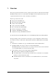
1. Overview This system performs file transfer and other operations between the Casio Data Collection Terminal IT-2000 (hereinafter referred to as this terminal or IT-2000) and an AT architecture-based personal computer (hereinafter referred to as PC or Host PC) via the I/O Box.
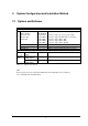
2. System Configuration and Installation Method 2.1 Options and Software Category Hardware Name Satellite I/O Box Master I/O Box RS-232C cable RS-422 cable SCSI cable Data Collection Terminal PC SCSI Board Software PC side Upload/Download Utility IT-2000 Windows3.1 ver. side FLINK Utility MS-DOS version FLINK Utility Table 2.
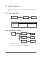
2.2 System Configuration This system can be configured in various ways. See typical examples of the hardware configuration as below. 2.2.1 With Single I/O Box RS-232C Satellite I/O Box IrDA IT-2000 PC Fig.2.1 System configuration with single Satellite I/O Box Hardware Software PC side Upload/Download Utility IT-2000 side Satellite I/O Box FLINK of Windows 3.1 ver. RS-232C cable or FLINK of MD-DOS ver. IT-2000 PC Table 2.2 Hardware and software configuration with single Satellite I/O Box 2.2.
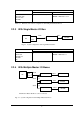
Hardware Software PC side IT-2000 side Satellite I/O Box Upload/Download Utility FLINK of Windows3.1 version or RS-232C cable FLINK of MS-DOS version RS-422 cable IT-2000 PC Table 2.3 Hardware and software configuration with multiple Satellite I/O Boxes 2.2.3 With Single Master I/O Box SCSI PC Master I/O Box SCSI IrDA IT-2000 Board Fig.2.3 System configuration with single Master I/O Box Hardware Software PC side Upload/Download Utility IT-2000 side Master I/O Box FLINK of Windows3.1 ver.
Hardware Software PC side IT-2000 side Master I/O Box Upload/Download Utility FLINK of Windows3.1 ver. or SCSI cable FLINK of MS-DOS ver. IT-2000 PC SCSI Board Table 2.5 Hardware and software configuration with multiple Master I/O Boxes 2.2.
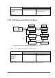
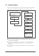
2.3 Installation Method This section describes the installation and setup procedures that must be performed before I/O Box and PC operations are started. The following diagram shows a flow of the setup procedure. Fig.2.6 Installation flow of IT-2000 (If Master I/O Box is used) Set the DIP switch of I/O Mount SCSI Board in the PC and Box. install the SCSI driver Connect each cable between Install Upload/Download I/O Boxes. Utility in the PC. Connect cable between the PC and I/O Box.
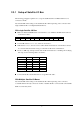
2.3.1 Setup of Satellite I/O Box The following paragraphs explain how to set up the Satellite I/O Box and Master I/O Box to be connected to the PC. Note that the DIP switch settings of the Satellite I/O Box differ depending on the connection with single Satellite I/O Box or multiple Satellite I/O Boxes. With single Satellite I/O Box Make sure that the POWER switch of the I/O Box is set to OFF.
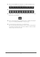
Make sure that the POWER switch of the I/O Box is set to OFF. Set the DIP switch of the first I/O Box to be connected to the PC directly as follows. 1 2 3 4 5 6 7 ON OFF OFF OFF OFF OFF ON 9 ON 10 ON Set the DIP switch of other I/O Boxes to be connected under daisy-chain as follows. 1 ON 8 ON 2 OFF 3 OFF 4 OFF 5 ON 6 OFF 7 ON 8 ON 9 ON 10 ON Set DIP switch no. 5 of the last I/O Box to ON if the C-OUT terminal does not connect another I/O Box (This is for the termination).
2.3.2 Setup of Master I/O Box Note that the DIP switch settings of the Master I/O Box differ depending on whether the system configuration is consisted of only single Master I/O Box or of multiple Master I/O Boxes that are followed by Satellite I/O Boxes. Make sure that the POWER switch of the I/O Box is set to OFF. Set the DIP switch at the rear of the unit as follows: 1 2 3 ON OFF OFF 4 OFF 6 OFF 5 ON 7 OFF 8 OFF 9 ON 10 ON Setup for the SCSI ID (DIP switches nos.
Power SCSI termination Supplies power Does not supply power 10 ON OFF Connect the first I/O Box and PC with the SCSI cable. Then connect the SCSI connector of the I/O Box connected to the PC to the SCSI connector of the other I/O Box via the SCSI cable. Connect the remaining I/O Boxes so that the one with the terminator setting becomes to the last under daisy-chain connection. Select a suitable cable that matches the shape of the connector on the PC side to connect the PC and the first I/O Box. 2.
2.3.4 Setup of PC Connection If using the Satellite I/O Box, plug the connection cable into the COM port of the PC. If using the Master I/O Box, plug the connection cable into the SCSI board of the PC. Startup First turn ON the power to each I/O Box, then turn ON the PC power to start up Windows95 and start up the Upload/Download Utility. Make sure that the Main Menu of the Upload/Download Utility appears. Fig. 2.
Environment Setup If the I/O Box to be connected to the PC is a Satellite I/O Box, select "RS-232C" from the "Configure" menu of the Upload/Download Utility, then select "Settings" from the same menu. Fig. 2.8 RS-232C Main Menu screen In the COM PORT field select the COM port number in the PC to be used. In the Baud Rate field select the communication speed (baud rate) of the RS-232C. Parity, Stop bit, and Data bits values should be as shown in the above figure.
3. Operation Method After connecting the necessary system devices and installing the software on the PC, perform file upload/download with the following procedure. On this system each function will be executed if the IT-2000, which has started up the FLINK Utility, is mounted on the I/O Box after the PC-side utility was started up. Each function can also be executed by initiating the PC-side utility after mounting the IT-2000, which has started up the FLINK Utility, on the I/O Box. 3.
Set any "Options" item, if necessary. Set the "Mode" option, if necessary. Click on the [OK] button. If preparation has been completed on the IT-2000 side, the progress bar will be displayed and file uploading will begin. If a communication anomaly occurs, an error message will be displayed and communication will be terminated. Operation on IT-2000 Start up MS-DOS. Start up FLINK without adding parameters. "Wait..." is displayed on the IT-2000 screen and the idle mode is set. FLINK.
3.1.2 Specifying Files from IT-2000 Operation on PC Start up the Upload/Download Utility on the PC and select "Link Manager Start" from the "Execute" menu. Fig. 3.2 Screen displayed after "Link Manager Start" If the preparation has been completed on the IT-2000 side, the progress bar will be displayed and the file upload will begin. If a communication anomaly occurs, an error message will be displayed and communication will be terminated. Operation on IT-2000 FLINK.
FLINK.DLL of Windows 3.1 version Start up Windows 3.1. Start up FLINK with the appropriate parameters. DoFLINK ( argc, argv ) argc = 4; argv[ ]= { "fl" , "/s", "D: FILE", "C: yy" } This transfers D: FILE from the IT-2000 to C: yy on the PC. If the preparation has been completed on the PC side, the progress bar will be displayed and file uploading will begin. If a communication anomaly occurs, an error message will be displayed and communication will be terminated.
3.2 File Download Transfer files from the PC to the IT-2000. There are two methods for specifying the files to be downloaded: specifying files from the PC, and specifying files from the IT-2000. 3.2.1 Specifying Files from PC Operation on PC Start up the Upload/Download Utility on the PC and select "Command" from the "Execute" menu to display the Command Screen. Set the Command field to "Send". In the "File(s)" field specify the name of the objective file on the PC by its full path name.
Operation on IT-2000 FLINK.EXE of MS-DOS version Start up MS-DOS. Start up FLINK without adding any parameters. "Wait..." is displayed on the IT-2000 screen and the idle mode is set. FLINK.DLL of Windows 3.1 version Start up Windows 3.1. Start up FLINK without adding any parameters. DoFLINK ( argc, argv) argc = 1; argv[ ]= { "fl" } "Wait..." is displayed on the IT-2000 screen and the idle mode is set.
3.2.2 Specifying Files from IT-2000 Operation on PC Start up the Upload/Download Utility on the PC and select "Link Manager Start" from the "Execute" menu. Fig. 3.4 Screen displayed after "Link Manager Start" If the preparation has been completed on the IT-2000 side, the progress bar will be displayed and file downloading will begin. If a communication anomaly occurs, an error message will be displayed and communication will be terminated. Operation on IT-2000 FLINK.
FLINK.DLL of Windows 3.1 version Start up Windows3.1. Start up FLINK with the receive mode option. DoFLINK ( argc, argv ) argc = 4; argv[ ]= { "fl" , "/r", "C: FILE", This transfers C: FILE from the PC to D: "D: yyy" } yyy on the IT-2000. If the preparation has been completed on the PC side, the progress bar will be displayed and file downloading will begin. If a communication anomaly occurs, an error message will be displayed and communication will be terminated.
4. Error Codes and Error Messages Any termination codes and error information generated by the PC will be recorded in the error log file on the PC. This error log file will be created according to the file name specified by the DEVICE.INI file (configuration file), and each new log entry will be appended to the file. This error log file cannot be automatically deleted. Therefore, it is recommended to check the contents when required and delete the file.
Error Code Error Message Description Remedy Categ. Detai 0x00 0xDC 0xF5 0xF8 0x01 0x01 0x01 0x01 0x01 0x01 0x01 0x01 0x00 0x00 0x00 0x00 0x00 0x01 0x02 0x03 0x04 0x05 0x06 0x07 NormalEnding ADriveFormatNotice ZDriveFormatNotice BreakKeyInterruptEndingNotice UndefineFunctionCode UndefineSubFunctionCode NotExecuteCommand CheckSumError CommandSequenceError SequenceNumberError OtherProtocolError ParameterError Normal end.
Er ror Error Code Error Message categ Detai 0x04 0x00 ReadOnlyFileAccessError Write is specified to read-only-file. 0x05 0x05 0x05 0x05 Communication error. Spawn error. Command timeout error. Fail to open log file. Description Remedy 0x05 0x06 OptionError Option error. 0x05 0x07 StartupError Startup error. 0x05 0x05 0x05 0x05 0x05 0x05 0x05 Open error. Listen error. Accept error. Memory is not enough. Process is too long. Child-process ends illegally. Child-process ends normally.
5. Q and A Common to Satellite and Master I/O Boxes Q1 It seems that it takes a rather long time for communication to start, doesn't it? A1 Communication between the IT-2000 and Satellite/Master I/O Box is performed according to IrDA protocol. Generally, the IrDA protocol requires 2 to 3 seconds until communication between the PC and IT-2000 is established. This period of time is required for each IT-2000 terminal.
Q2 If the Windows3.1 version of FLINK is used, the baud rate setup cannot be modified by changing the DIP switch setting for the RS-232C communication speed on the Satellite I/O Box. Why? A2 To modify the RS-232C communication speed with the Windows3.1 version of FLINK, it must be started up with the following option. Otherwise, the default value of 9600 bps is automatically used.
Q2 What is the maximum baud rate if the Satellite I/O Boxes are connected under daisy-chain so they follow each Master I/O Box ? A2 In this case the physical Master I/O Box-to-Satellite I/O Box speed is 115200 bps max. Q3 Can I update the version of Master I/O Box firmware ? A3 Yes, by using the dedicated download tool and a SCSI cable. Your nearest support/technical center will inform you if it is necessary.
6. Reference Manuals Besides this IT-2000 I/O Box Installation Manual, the following manuals are available for the IT-2000 system as application program development manual.
7. List of SCSI Boards and SCSI Cables The listed SCSI Boards and Cables below have been assessed for the operability with the IT-2000. Thus, they are recommended for use with the IT-2000. Manufacturer Model SCSI Board Adaptec AHA1540CP Adaptec AHA2940AU Adaptec AHA1510B Adaptec AHA1542CF SCSI Cable Casio SB-751HF Casio SB-752HH Casio SB-753HP Table 7.
Appendix Installation Method of Upload/Download Utility Installation The Upload/Download Utility software consists of the following software components: File name LMWIN32.EXE driver32.dll hfc32.dll Iman32.dll scsidrv.dll tcpip.dll LMWIN.INI DEVICE.