
User Manual


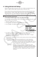


Table Of Contents
- 目录
- 介绍 — 请首先阅读这一部分!
- 第1章 基本操作
- 第2章 手动计算
- 第3章 列表功能
- 第4章 方程计算
- 第5章 绘图
- 第6章 统计图形与计算
- 第7章 财务计算(TVM)
- 第8章 编程
- 第9章 电子表格
- 第10章 eActivity
- 第11章 存储器管理器
- 第12章 系统管理器
- 第13章 数据通信
- 第14章 PYTHON(仅限fx-9860GIII, fx-9750GIII)
- 第15章 分布(仅限fx-9860GIII, fx-9750GIII)
- 附录
- 考试模式(仅限 fx-9860GIII/fx-9750GIII)
- E-CON3 Application (English) ( fx-9860GIII, fx-9750GIII)
- 1 E-CON3 Overview
- 2 Using the Setup Wizard
- 3 Using Advanced Setup
- 4 Using a Custom Probe
- 5 Using the MULTIMETER Mode
- 6 Using Setup Memory
- 7 Using Program Converter
- 8 Starting a Sampling Operation
- 9 Using Sample Data Memory
- 10 Using the Graph Analysis Tools to Graph Data
- 11 Graph Analysis Tool Graph Screen Operations
- 12 Calling E-CON3 Functions from an eActivity

• From the menu that appears after you select “Photogate” as the sensor, select
[Gate] or [Pulley].
[Gate] ................Select this option when using the Photogate sensor alone.
[Pulley] ..............Select this option when using the Photogate sensor along with a
smart pulley.
5(None) ......... Select this option to disable the SONIC channel.
• Mic Channel (EA-200 only)
For this channel, the sensor is automatically set to Built-in (External) Microphone.
However, you need to configure the settings described below.
1(Snd) ........... Select this option to record elapsed time and volume 2-dimensional
sampled sound data (elapsed time on the horizontal axis, volume on
the vertical axis).
2(FFT) ........... Select this option to record frequency and volume 2-dimensional
sampled sound data (frequency on the horizontal axis, volume on the
vertical axis).
5(None) ......... Select this option to disable the Mic channel.
4. Repeat steps 2 and 3 as many times as necessary to configure all the channels you want.
5. After all the settings are the way you want, press w.
• This returns to the Advanced Setup menu.
Note
• When you select a channel on the Channel Setup screen, the sampling range of the
selected channel appears in the bottom line of the screen.
In the above example, the range of the temperature sensor assigned to CH2 appears on the
display.
If the sampling range value is too long to fit on the display, only the part of the value that fits
on the display will be shown.
• Whenever the current Sample Setup (page 3-5) and Trigger Setup (page 3-8) settings
become incompatible due to a change in Channel Setup settings, these settings revert
automatically to their initial defaults. Selecting the Mic channel with Channel Setup while
the Sample Setup has “Extended” selected for the sampling mode, for example, will cause
the sampling mode to change automatically to “Fast” (which is the initial default setting
when the Mic channel is selected). For information about the channels that can be selected
for each sampling mode, see “Sample Setup” (page 3-5).
3-4
Using Advanced Setup