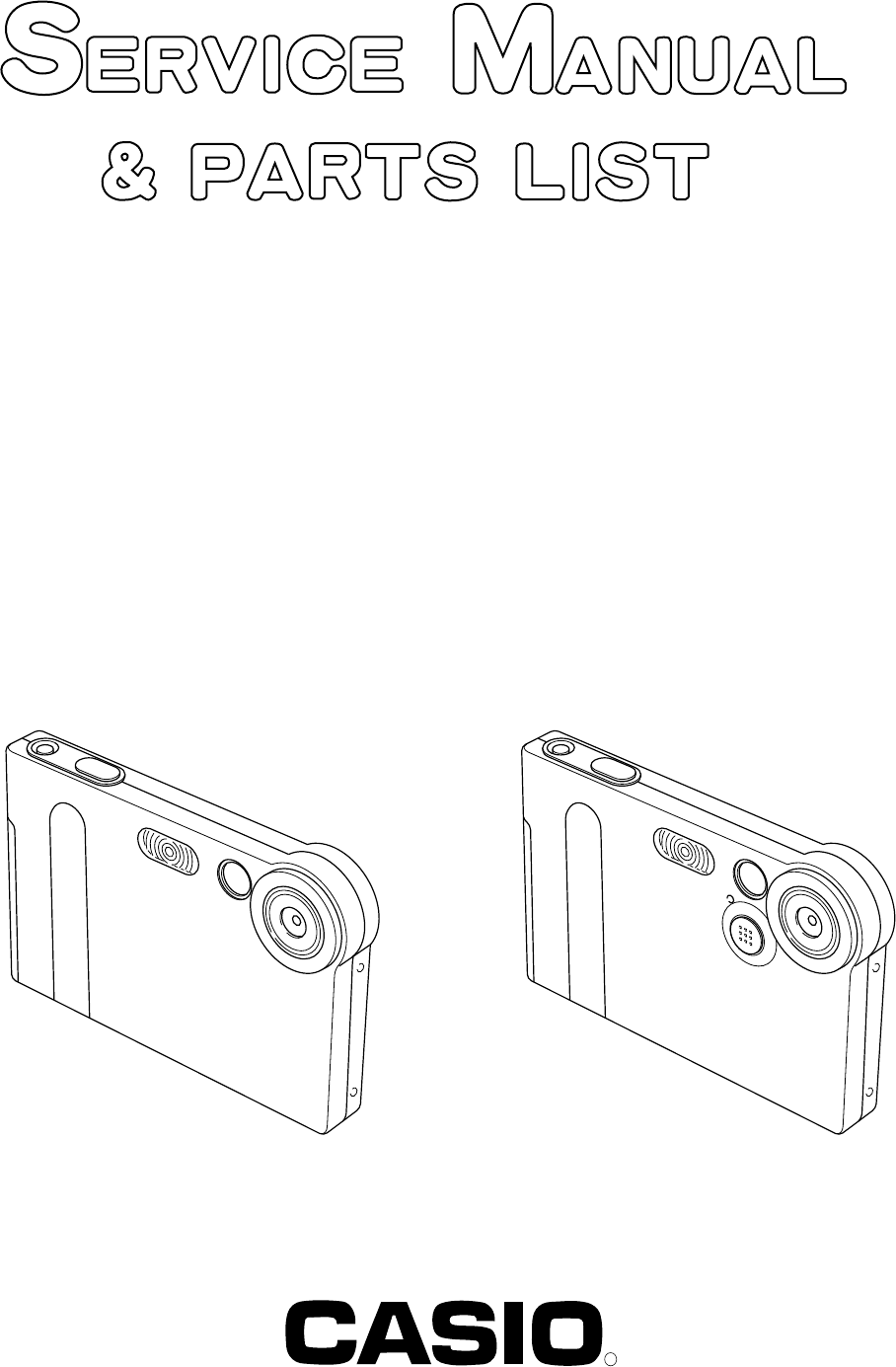
(without price) EX-S1/M1 JUN. 2002 EX-S1 EX-M1 INDEX R Ver. 2 Ver.
CONTENTS SPECIFICATIONS ....................................................................................................................................... 1 TEST MODE ................................................................................................................................................ 4 PROGRAM VERSION UPGRADING .......................................................................................................... 5 1. How to confirm the program version ....................
SPECIFICATIONS Image Files Format Snapshots: JPEG (Exif Version 2.2); DCF (Design Rule for Camera File System)1.
Exposure Control Shutter Metering: Multi-pattern by imaging element Exposure: Program AE Exposure Compensation: –2EV to +2EV (in 1/3EV steps) CCD shutter, mechanical shutter 1/4 to 1/8000 second Aperture F2.
Dimensions EX-S1: 88(W) x 55(H) x 11.3(D) mm (3.5˝(W) x 2.2˝(H) x 0.4˝(D)) (excluding projections) EX-M1: 88(W) x 55(H) x 12.4(D) mm (3.5˝(W) x 2.2˝(H) x 0.5˝(D)) (excluding projections) Weight EX-S1: Approximately 85 g (3.0 oz) (excluding battery and accessories) EX-M1: Approximately 87 g (3.
TEST MODE Note: Do not perform the menu item unless explained here. (It may damage the internal data and camera becomes unusable.) Booting To boot the test mode While firmly pressing down both "MENU" and "SET" buttons, Turn the power on. Continue pressing "MENU" and "SET" until the MAIN MENU is displayed. 2 "POWER" button 1 "MENU" + "SET" buttons While holding the camera in a horizontal position, press the set button twice towards your "RIGHT" and then press "MENU" .
PROGRAM VERSION UPGRADING ■ Introduction Update the program using an SD card. Note: Make sure to use a fully charged battery. MAIN PCB becomes unusable if power down or an error occurs during program transmission. 1. How to confirm the program version ■ The program version can be confirmed in the test menu (refer to the previous page). ■ Turn the power on while pressing MENU button. The following program version also can be found. Check the LCD display. (Example) VER 1.00 (As of May 28. 2002) 2.
7. If the version is correct, turn the power off. 8. Finally, check the operation by recording, playing back and deleting an image. 3. How to recover the program in case of the failure 1. Prepare the following firmware restoration program and change its name to "mercury.bin". EX-S1 : kx851r.hbn EX-M1 : kx852r.hbn • Insert the SD card into the computer using the PC card adaptor. * Prepare the PC card adaptor for the SD card. • The computer recognises the SD card as a "REMOVABLE DISK". 2. 3. 4. 5.
COLOR ADJUSTMENT ■ Introduction Make sure to perform the adjustment when replacing the lens unit or the MAIN PCB. The necessary software, driver and setting are explained in using USB ADJ Tool "adj331e.exe (Ver.1.1). Note that the tool, drivers etc. are available only for Windows. 1. How to use USB ADJ Tool 1-1. Prepare the necessary software, driver and DLL file. (1) Prepare the following three files. • Commom test driver for CASIO/PENTAX [testmode_pentax_casio] folder uusbd.dll uusbd.inf uusbd.
NOTE: How to uninstall the USB driver for the USB test mode • Connect the camera while in the USB test mode to the computer so that the computer recognises the camera. • Right-click "My computer", select "Property" and open "Device manager". • Select "USB device for UUSBD" , and then "Universal USB Driver (VMEM manufacturer's name)". • Press "Delete" button and delete the driver. • When using Windows98/98SE/Me, delete the following three files; (NOTE! Do NOT delete "usbd. inf" and "usbd.
2. Lens Replacement Make sure to perform the following procedure after replacing the lens. A foppy disk with the lens data is bundled in the spare parts of the lens unit. 1 Enter the TEST mode. 1.Turn the power on while pressing both "MENU" and "SET" buttons. 2.Press "RIGHT" button, "RIGHT" button and "MENU" button while the program version is displayed. 3.Select "3.USB TCC TEST". 4.Select "1. USB TCC ON". 5.Turn the power OFF.
5 Save the information in the computer. 6 Replace the MAIN PCB. 7 Perform the above 1 to 3 after replacing the MAIN PCB without any problem. 8 Open the file which is saved above. 9 Click "WRITE" button of "ADJ ALL". 0 After adjustment, change "1. USB TCC ON" to "2. USB TCC OFF". 5 8 9 4 4. Operation and Current consumption 1.
DISASSEMBLY NOTE : Here EX-M1 is used. 1. Remove the CARD, BATTERY and the JACK COVER. 2. Remove five screws. Screws Screws Screw 3. Remove the REAR CASE ASSY.
4. Removing the LCD ASSY 1 Remove the hook from the MAIN PCB and slide the LCD ASSY. 2 Remove the CONNECTOR. 3 Remove the LCD ASSY. 1 2 3 Connector NOTE: Fix the FPC to the CONNECTOR tightly when assembling. 5. Remove the FPC from the CONNECTOR and then remove the SW UNIT.
6. Removing the SUB PCB ASSY 1 Unsolder the five lead wires. 2 Remove the hook and then the SUB PCB ASSY. The SUB PCB is connected to the MAIN PCB by the CONNECTOR. Note in assembling *1 Position these four lead wires in the space between the MAIN PCB and the SUB PCB. *2 Make sure that this lead wire does not touch the battery spring. × 2 *1 × 2 *1 1 × 1 *2 2 7. Removing the STROBE UNIT (NOTE: The STROBE UNIT does not need be discharged.) 1 Remove the STROBE PLATE.
8. Removing the LENS UNIT 1 Remove the CONNECTOR. 2 Remove the LENS UNIT while taking care of the hook. Hook 9. Remove the MAIN PCB. 10. Remove the microphone (EX-M1 only).
22 14 13 7 S1 19 4 2 10 20 11 S1 21 — 15 — 1 12 18 8 S1 15 5 6 17 16 Dumy Card/ SD Card EXPLODED VIEW 3 9
PARTS PRICE LIST EX-S1/M1 N Parts Code Item Parts Name Specification QTY EX-S1 EX-M1 Price Code R N 1 10085205 LENS UNIT RJK503328*001V01TK 1 1 DI B N 2 10085206 ASSY / FRONT CASE RJK502949*001V01TK 1 0 CN C N 2 10084967 ASSY / FRONT CASE RJK502953*001V01TK 0 1 CQ C N 3 10085208 ASSY / REAR CASE RJK502892*001V01TK 1 0 CH C N 3 10084968 ASSY / REAR CASE RJK502952*001V01TK 0 1 CF C N 4 10085223 ASSY / BATTERY COVER RJK502891*001V01TK 1 1 AN B N 5 10085
PRINTED CIRCUIT BOARDS MAIN PCB TOP VIEW — 17 —
MAIN PCB BOTTOM VIEW — 18 —
SUB PCB TOP VIEW BOTTOM VIEW — 19 —
SCHEMATIC DIAGRAMS MAIN PCB — 20 —
SUB PCB (EX-S1 only) — 21 —
SUB PCB (EX-M1 only) — 22 —
Ver.1 : (1) The button to be pushed in the test mode has been changed. (page 4 and 9) (2) The following items were changed. · PARTS LIST (page 16) Ver. 2 : Correction of page 4, 5, 6, 7, 8, 9, 10 and 16. CASIO TECHNO CO.,LTD. Overseas Service Division Nishi-Shinjuku Kimuraya Bldg.