DT-X5 Series Hardware Manual (Version 1.04) CASIO Computer Co., Ltd. Copyright ©2006. All rights reserved.
Table of Contents Chapter 1 1.1 1.2 1.2.1 1.3 1.3.1 1.3.2 1.3.3 1.3.4 Chapter 2 2.1 2.1.1 2.1.2 2.2 2.3 2.4 2.5 2.6 2.7 2.8 Chapter 3 Chapter 4 4.1 4.1.1 4.1.2 4.1.3 4.1.4 4.1.5 4.2 4.2.1 4.2.2 4.2.3 4.2.4 4.2.5 4.3 4.3.1 4.3.2 4.3.3 4.3.4 4.4 4.4.1 4.4.2 4.4.3 4.5 4.5.1 4.5.2 4.5.
Chapter 5 5.1 5.2 Chapter 6 6.1 6.2 6.2.1 6.2.2 Cable Specifications For Chain Connection and Short Length For Chain Connection and Long Length Precautions Handling Precautions Safety Battery Pack General 45 45 46 47 47 48 48 49 CASIO is a registered trademark of CASIO Computer Co., Ltd. in Japan. Other product names or company names in this reference manual are either trademarks or registered trademarks of their respective owners.
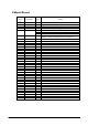
Editorial Record Manual Version no. 0.90 1.00 1.01 1.02 1.03 March 2004 August 2004 September 2004 February 2005 August 2006 1.04 September 2006 Date edited Page 36 all 7 9 32 7 Content Tentative version Original version The content in Table 4.11 of Chapter 4 has been updated. The description about C-MOS imager has been added. The content in Table 1.2 of Chapter 1.2 is updated. The content in Fig. 1.2 of Chapter 1.2.1 is corrected. The content in Table 2.14 of Chapter 2.7 is updated.
Preface A new industrial handheld terminal has been developed. CASIO introduces the DT-X5 series of handheld terminal with built-in SH-3 (32-bit RISC type) Processor, high speed laser scanner and diverse wireless LAN communications via Bluetooth as standard and IEEE802.11b WLAN (model dependent). Running under Microsoft Windows CE .NET4.1 operating system, the rugged DT-X5 is designed specifically for industrial applications.
1. Overview 1.1 Features Incorporates .NET technology • • • Uses WindowsCE .NET 4.1 operating system. Makes effective use of .NET resources developed by other parties. Employment of Embedded OS makes it possible to build a flexible WindowsCE system. Enhanced communicating functions • • • • Built in Bluetooth Ver 1.1 module. The transfer rate of the Wireless LAN (model dependent) is 5 Mbps, which is the maximum rate of communication for peer-to-peer connection with PC over IEEE802.11b.
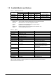
1.2 Available Models and Options Table 1.1 Models of DT-X5 series Wireless LAN Model IEEE802.11b Bluetooth DT-X5M10E No Yes DT-X5M10R ETSI Yes DT-X5M30E No Yes DT-X5M30R ETSI Yes DT-X5M30U No Yes IEEE802.11b Bluetooth C-MOS Laser Lithium-ion Alkaline Table 1.
The accessories in the table below are accompanied as accessory in each individual carton box of DT-X5. Table 1.
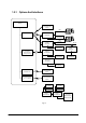
1.2.1 Options And Interfaces DT-X5 IrDA Printer ( Recommended Option) USB IrDA Ver. 1.1 Bridge Basic Cradle HA-A60IO PC AC Adaptor AD-S42120AE Bridge Satellite Cradle HA-A61IO Power Supply Terminals ( Built-in Battery Charge Circuit) USB RS-232C RS-422 PC RS-422 AC Adaptor AD-S42120AE Bridge Satellite Cradle HA-A61IO AC Adaptor AD-S42120AE AC Adaptor AD-S42120AE Cradle-type Battery Charger HA-A30CHG Battery Charger Car Mount Unit HA-A34AT Car Power Cable DT-827CAC SS? ? WLAN ?? ? ( IEEE802.
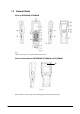
1.3 General Guide Views for DT-X5M10E, DT-X5M10R Fig. 1.3 Note: The front view in Fig. 1.3 is for all the models of DT-X5 series. Views for side and back of DT-X5M30E, DT-X5M30U and DT-X5M30R 22 Fig. 1.4 Refer to Table 1.4 “Names of parts” in the following page for each part and its description.
Table 1.4 Names of parts No.
1.3.1 HA-A34AT Battery Charger Car Mount Unit View Power Indicator Lamp Power Contacts HA-A30CHG HA-A34AT Power Switch Car power code jack Remove button Fig. 1.5 Note: The view in Fig. 1.5 shows HA-A34AT (Battery Charger Car Mount Unit) with HA-A30CHG (Cradle-type Battery Charger) integrated to it.
1.3.2 HA-A61IO and HA-A60IO Cradles Views 1 Top 2 3 Right Front Back 4 5 11 7 6 12 13 10 Bottom 8 9 Fig. 1.6 Refer to Table 1.5 “Names of parts” in the following page for each part name and its description.
Table 1.5 Names of parts No. Part Name 1 IR port 2 3 4 Terminal detect switch Power contacts Fall protector 5 Power indicator lamp 6 Communication indicator lamp 7 System status indicator lamp 8 Desktop unit 9 DIP switches (HA-A61IO only) Power switch Wall mount unit fastening plate AC adaptor jack RS-422 port (HA-A61IO only) RS-232C port (HA-A61IO only) 10 11 12 13 14 15 USB port Description This port transfers data with the terminal IR port non-contact communication.
1.3.3 DT-5022CHG Dual Battery Charger Views Charge status indicators Top Battery pack compartments Dual charger connection terminals Right Left AC adaptor jack Bottom Connection attachments Fig. 1.
1.3.4 HA-A20BAT and DT-5025LBAT Battery Packs Views HA-A20BAT Left DT-5025LBAT Top Left Side Top Side Charge/Power supply terminals Charge/Power supply terminals Bottom Bottom Fig. 1.
2. Hardware Specifications 2.1 DT-X5 Table 2.1 Item CPU, Memory CPU Operating system RAM FROM (OS) FROM (Storage) Laser scanner Method Laser emitting window Wave length Output power Scanning speed Resolution PCS Depth Readable width Readable symbologies Ambient light immunity C-MOS imager Method Emitting window Resolution PCS Depth Readable width Readable symbology Display Display device No. of dots Dot pitch Scale Display fonts Backlight Indicator Confirmation /Status Continue.
Input Keyboard Control keys Trigger keys IrDA Standard Method Synchronization Baud rate Comm. range WLAN Standard Modulation Frequency range Baud rate Comm. range No. of channels Output power Other feature Bluetooth Standard Comm. range Output power Wake-up function Buzzer Sound pressure Vibrator Cursor up-and-down key, L and R keys, Ten keys (0 to 9), Fn key, Multi key, Function keys (F1 to F8) Power key, Reset switch 2 pcs (on the left and right sides) IrDA Version 1.
Lithium-ion battery pack charge time HA-A20BAT DT-5025LBAT Memory backup battery charge time Approx. 4 days : Approx. 5 hours : Approx. 10 hours Conditions; - The power switch is turned off. - The lithium-ion battery pack is a brand new. - The surrounding temperature is at room temperature. Conditions; - Lithium-ion battery pack is installed. - The surrounding temperature is at a room temperature. Dimensions Approx. 54 (W) x 179 (D) x 21.4 (H) mm Note 4 Weight Note 5 DT-X5M10E, M30E, Approx.
Table 2.2 Operating hours by model Model WLAN IEEE802.11b Scan engine DT-X5M10E No Laser DT-X5M10R DT-X5M30E, DT-X5M30U DT-X5M30R Yes No Yes Laser C-MOS C-MOS Battery Operating hour Alkaline batteries HA-A20BAT DT-5025LBAT HA-A20BAT DT-5025LBAT HA-A20BAT DT-5025LBAT HA-A20BAT DT-5025LBAT Alkaline batteries HA-A20BAT DT-5025LBAT HA-A20BAT DT-5025LBAT HA-A20BAT DT-5025LBAT HA-A20BAT DT-5025LBAT Approx. 200 Approx. 90 Approx. 180 Approx. 90 Approx. 180 Approx. 15 Approx. 30 Approx. 20 Approx.
Table 2.
2.1.1 Reference for Laser Scanner Performance Reference of the laser scanner performances below for the DT-X5M10E/DT-X5M10R is provided as a guide to be utilized by the user. The user can refer to these reference values in the table for his or her specific business application. All the reference values have been came out from the assessment tests carried out under the basic performance conditions below.
0 to50 0 to 60 Resolution 0.25 0.33 0.5 1.0 0 to 150 0 to 200 0 to 300 0 to 400 Fig. 2.
2.1.2 Reference for C-MOS Imager Performance Reference of the C-MOS imager performances below for the DT-X5M30E, DT-X5M30R and DT-X5M30U is provided as a guide to be utilized by the user. The user can refer to these reference values in the table for his or her specific business application. All the reference values have been came out from the assessment tests carried out under the basic performance conditions below.
Basic scanning conditions: Test chart Resolution PCS Read judgment Depth Pitch angle Skew angle Tilt angle Surrounding temperature Surrounding humidity Surrounding illumination Background of the symbol Conditional Judgment : Dedicated test pattern (1D, 2D Stacked) : 1D 0.25 mm / 2D 0.5 mm : 0.9 or greater : 7 times per 10 scans First Decode : 110 mm from the LED emission port : α = 0 degree : β = 10 degree : γ = 0 degree : 25 ºC : 30 to 50% : 450 to 550 Lux.
2.2 HA-A60IO, HA-A61IO Table. 2.7 Item USB 11 1 22 2 4 4 3 Connector 1. VBus 2. –Data (D-) 3. +Data (D+) 4. GND 3 USB connector type B Full duplex Start/stop method 115.2 Kbps Comm. method Synchronization Comm. speed Applicable to HA-61IO only. SG ER SD RD CD RS-232C S E S R C 5 4 3 2 1 9 8 7 6 CI C CSC RS R DD D-Sub 9-pin (Male) Full duplex Start/stop method 115.2 Kbps IN OUT No. of LEDs Status LED No.
Power contact Power contact GND The illustration of the power contact on the left is viewed at the front of the cradle. Weight/Dimensions Table 2.8 Model no. Configuration In desktop state In wall mount state Dimensions In desktop state In wall mount state Weight In desktop state In wall mount state Dimensions In desktop state In wall mount state Weight HA-A61IO HA-A60IO 27 Specification Approx. 530 g Approx. 620 g Approx. 110 (W) x 125 (D) x 128 (H) mm Approx.
2.3 HA-A34AT Table 2.9 Item Display Input Power Specification Remark No. of LEDs 1 No. of display colors 2 In red and green Display content Power status (“POWER”) Status LED Indicates the status of terminal being mounted on the charger. OFF : Power is off. Flashing in green : Power is on and the terminal is mounted on the charger. Flashing in red : Power is on but the terminal is not mounted on the charger.
2.4 HA-A30CHG Table 2.11 Item Display Input Power No. of LEDs Status LED No. of display colors Display content Detection switch for DT-X5 Input voltage Consumption current Input from AC adaptor Plug AC adaptor Output voltage Output current Charge method Charge/Power supply Specification 1 2 Power status (“POWER”) Push switch DC 12V±5% Approx. 3.5A EIAJ RC-5320A Class 4 AD-S42120AE DC5V±10% 1,500 mA (maximum) Constant voltage Approx. 4 hours Approx.
2.5 DIP Switch Setting for HA-A61IO The DIP switch is located on the rear side of the Bridge Satellite Cradle. Change the ON/OFF settings according to your required system configuration. The new settings do not go into effect until the power switch is turned off and then back on again.
2.6 Status Indications with LEDs Various operational statuses on the HA-A61IO can be displayed using the LEDs. The following table describes LED modes and their meanings. Table 2.13 Item LED Power status indicator (POWER) Comm. status indicator (DATA) (HA-A61IO only) Line status indicator (LINE) Specification Power off. Power is on and the terminal is mounted correctly. Power is on but the terminal is not mounted correctly. No communication being performed. Communication is in progress.
2.7 DT-5022CHG Basic Block Table 2.14 Item Basic function Rechargeable battery pack HA-A20BAT DT-5025LBAT AC adaptor AD-S45150AU AD-S45150AE Specification Remark Battery pack (1,700 mAH) Large-capacity size battery pack (3,400 mAH) Dedicated batteries only. Input; 100 to 230VAC Input; 100 to 230VAC With US power cord With European power cord Interface Block Table 2.
Battery Charge Block Table 2.17 Item Specification Charge control Output voltage DC4.22V±30mV Charge current (standard mode) DC1,600mA±10% Charge current (standby mode) DC160±40mA Full charge detection current DC120±30mA Voltage control Full charge detection voltage 4.1V Re-charge detection voltage 4.0V Re-charge detection voltage DC4.0±0.1V Input voltage DC8.
2.8 HA-A20BAT, DT-5025LBAT Table 2.19 Item Rated capacity Rated voltage Discharge end voltage Standard charge current Charge voltage Charge hour (standard mode) Weight Dimensions Specification HA-A20BAT 1,700 mAH 3.7V 2.75V 1.0 CA (=1.55A) 0 to 40 °C 4.2±0.05V 2.5 hours DT-5025LBAT 3,400 mAH 3.7V 2.75V 1.6A 0 to 50 °C 4.2±0.05V 5.0 hours Approx. 45 g 57 (L) x 37 (W) x 13 (H) mm Approx. 87g 57 (L) x 37 (W) x 24 (H) mm 34 Remark 0.2C discharge 0.
3. Product Identification and Reference Numbers On the back of the terminal and its options (major options only), there is a bar code and numbers printed on label as shown in Fig. 3.1 below. This bar code is represented by 15 digits of Code128 and by alphanumeric characters beneath the bar code. The numbers from 1 to 9 in the figure represent identification and references of the terminal. The numbers from 10 to 14 represent a manufacturing reference which is reserved by the manufacturer.
4. Quality References This chapter describes about references of the DT-X5 and its dedicated options concerned with environmental performance, compliance, mechanical and electric durability, etc. 4.1 Environmental Performances 4.1.1 DT-X5 Table 4.1 Item Specification Condition Temperature Operation -20 ºC to 50 ºC Non-operation -20 ºC to 70 ºC 0 to 40 ºC while mounting on Cradle.
4.1.2 HA-A60IO, HA-A61IO, HA-A30CHG Table 4.2 Item Specification Temperature Operation Storage 0 ºC to 40 ºC -10 ºC to 50 ºC Humidity Operation Storage Storage in carton box Temperature Humidity Dust and water-splash proof 30% to 80%RH (No condensation) 30% to 90%RH (No condensation) -10 ºC to 50 ºC 30% to 90%RH Not applicable.
4.1.3 HA-A34AT Table 4.3 Item Specification Condition Temperature Operation Storage 0 ºC to 40 ºC -40 ºC to 85 ºC Humidity Operation Storage Storage in carton box Temperature Humidity 30% to 80%RH (No condensation) 30% to 95%RH (No condensation) -10 ºC to 50 ºC 30% to 90%RH 4.1.4 DT-5022CHG Table 4.4 Item Specification Condition Temperature Operation Non-operation Storage 0 to 40 ºC -10 to 50 ºC -10 to 55 ºC When battery is not charged.
4.2 Electrical Performances 4.2.1 DT-X5 Table 4.6 Item Power consumption Anti-static strength Malfunction Destruction Specification DC1.1A/3.0V to 5V DC1.3A/3.0V to 5V DC1.4A/3.7V to 5V DC1.6A/3.7V to 5V Remark For DT-X5M10E For DT-X5M30E/DT-X5M30U For DT-X5M10R For DT-X5M30R ±4 KV (contact), ±8 KV (in air) ±12 KV Compliant with EN6100-4-2 4.2.2 HA-A60IO, HA-A61IO, HA-A30CHG Table 4.7 Item Current consumption Input voltage Specification Approx. 0.02 A/DC12V (HA-A60IO) Approx. 0.
4.2.4 DT-5022CHG Table 4.9 Item Anti-static strength Malfunction Destruction Specification ±5 KV ±10 KV Remark ESD method: 250 pF, 100 ohm Probe: Finger type Polarity: ± 4.2.5 HA-A20BAT, DT-5025LBAT Table 4.
4.3 Mechanical Performances 4.3.1 DT-X5 Table 4.11 Item Specification Resistance to drop impact (height) In bare condition 180 cm In individual carton box 70 cm or less In master carton box 70 cm or less Resistance to vibration 1.5 G or less Condition Onto concrete, one time on each of the 6 sides and 4 corners. Onto concrete, one time on each of the 6 sides, 1 corner, 3 edges. 10 to 55 Hz In X,Y, and Z directions Reciprocally for 30 minutes 4.3.2 HA-A60IO, HA-A61IO, HA-A30CHG Table 4.
4.3.4 HA-A20BAT, DT-5025LBAT Table 4.14 Item Resistance to vibration Specification 1.5 G or less Condition 10 to 55 Hz In X,Y, and Z directions Reciprocally for 30 minutes Resistance to impact In bare condition In individual carton box 100 cm 70 cm or less 6 faces, 4 edges onto P-tile. 6 faces, 3 edges, 1 corner onto P-tile.
4.4 Reliability 4.4.1 DT-X5 Table 4.
4.5 Compliance 4.5.1 DT-X5 EMC, EMI, Safety, WLAN /Bluetooth type approvals Table 4.18 Model EN301.489-17 (EMI,EMS) Compliance Standard Europe EN60825 EN300.328-2 (Laser) (Bluetooth, WLAN) EN60950 (Safety) DT-X5M10E Yes DT-X5M10R Yes DT-X5M30E Yes DT-X5M30R Yes Columns in gray color: not applicable. Yes Yes Yes Yes Yes Yes Yes Yes Yes Yes Yes Yes EN50371 EN50361 EN50360 (SAR) Yes Yes Yes Yes Table 4.
5. Cable Specifications 5.1 For Chain Connection and Short Length Length; 1 meter or less M a x m im u m 1m View from side View from top 1 2 3 4 5 6 1 2 3 4 5 6 C a b le ( s e e T a b le 5 . 1 ) M o d u la r p l u g ( c o m p p a t i b le w it h 6 /6 -6 F R S Y K (S a b y o In d u s tr ia l) Fig. 5.1 Table 5.
5.2 For Chain Connection and Long Length Length; 1 meter or longer View from side Max. 1,000m View from top 123456 123456 Modular plug compatible with 6/6-6 FR SYK50 by Sanyo Industrial Co. Cable compatible with SK-UTP 100M3P by Sanyo Industrial Co. Fig. 5.3 Pin layout diagram of cable for chain connection and long distance (pin-to-pin straight/twist-pair connection) Wiring Cradle at lower position under the chain connection Pin no.
6. Precautions 6.1 Handling Precautions Precautions for short-term storage (1 to 2 days) • • If the DT-X5 is to be stored over holidays (including Saturday and Sunday), replace the battery pack (or AA-size alkaline batteries) with brand-new one before starting the holiday. This will conserve the built-in memory backup battery and ensure retention of data on the terminal. If there is a possibility of the above or operator error (e.g.
6.2 Safety 6.2.1 Battery Pack • • • • • • • • • • • • • • Never disassemble or retrofit the battery pack. The battery pack has safety mechanism and protection means incorporated to avoid hazards. Should they be damaged, the battery pack could become hot, generate smoke, explode, or ignite. Never contact the “+” and “-“ terminals with metal objects such as a wire. Also, do not carry or store the battery with a metal necklace or hair pin.
6.2.2 General • • • • • • • • Be aware of abnormal conditions. If the DT-X5 is continuously used in an abnormal condition, a fire or electric shock may occur. If there is an abnormality, immediately turn off the Power switch, and be sure to remove the batteries and then contact a CASIO distributor for repair. Supply Current/Voltage Do not use the AC adaptor with an AC voltage not rated on the AC adaptor. Also, avoid drawing power from an outlet used for multiple devices.
• • • • • About the battery 1. Do not attempt to disassemble or solder the battery. Also, do not heat or throw the battery into a fire. 2. When the button-type battery (memory backup battery) used in this terminal is removed, exercise care so as not to accidentally swallow it. Remain aware of the danger to infants. Store the button-type battery in an infant-safe location. Should the battery be swallowed, immediately consult a doctor. 3.