CASSIOPEIA DT-10 Pegasus Settings User’s Guide Ver 1.00 Copyright© 2005 CASIO COMPUTER CO., LTD. All rights reserved.
変 更 履 歴 No Revision 更新日 項 1 1.00 05/2/22 初版 改訂内容 初版発行 2 3 4 5 6 7 8 9 10 11 12 13 14 15 16 17 18 19 20 21 22 23 24 25 Copyright© 2005 CASIO COMPUTER CO., LTD. All rights reserved.
1 Table of Content 1 PEGASUS SETTINGS FOR POCKET PCS ..............................................................................................................1 1.1 PEGASUS CARD CONFIGURATION FOR POCKET PCS ................................................................................................1 1.1.1 1.1.2 1.1.3 1.1.4 1.2 Status Tab..........................................................................................................................................................
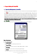
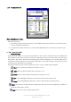
1 1 Pegasus Settings for Pocket PCs 1.1 Pegasus Card Configuration for Pocket PCs You need to configure the Pegasus card before you can be connected to the network. The Pegasus Configuration under Start->Settings->Connections can lead you to the configuration window. Tap on the icon Icon will take you to the Status (or Configuration) window of the Pegasus wireless settings. Here you will see four tabs: Status, Configuration, Advanced, and About tabs.
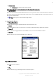
2 • Station IP Info IP Address – IP address of the card or module Note: Check with your network administrator for IP configuration information. • BSS ID/IBSS ID Shows the Network Name and the MAC address of the access point the card is associated with in the AP mode. Or it shows the Network Name and the MAC address of the creator of IBSS which the card is joined into in the Peer-to-Peer (Ad-Hoc) mode. • Help button: open a context sensitive help window. 1.1.1.
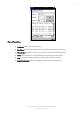
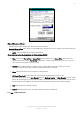
3 Figure 3 Ping window IP Address: Enter an IP address to ping. Size (Bytes): Choose from pull down menu from 32 to 8192 with 32 as the default. Timeout (ms): Defaulted to 500, can be increased or decreased from the spin button. Clear: Click this button to clear IP Address input and the ping statistics field. Ping: Click on this button to ping the IP address entered in the input field. Ping Statistics Field: Shows the pinging IP address and the pinging results.
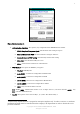
4 1.1.2 Configuration Tab Figure 4 Configuration window This window provides 1) Periodically updated scanning results in the Active SSIDs window that lists all the access points and peer stations available around the host. 2) A configuration tool that enables you to create and edit SSID profiles for your station to associate or join with. 1.1.2.1 Information Fields • Preferred Profiles On the top of the window is a list of preferred profiles one has created, or added from the Active SSIDs table below.
5 • Active SSIDs The Active SSIDs table lists all the access points or peer stations (creator of IBSS) in the vicinity with each record displaying the following six fields (The table may not display all the fields on the screen. Use horizontal scroll bar to check all): SSID – Network Name of the access point or peer station. A link icon with signal strength is also shown. Signal – Signal Strength in percentage for that SSID.
6 Figure 5 Network profile tab The information fields and operation buttons are listed as follows: Network Name & Type block: Used to create SSID with a network Type, and to configure the transmit data rate at certain channel. • SSID: to enter an SSID, which is the Network Name. Check with your network administrator for Network Name (SSID). • Type: Choose from Peer-to-Peer or Access Point in the pull down menu. Access Point (AP) mode is also called “Infrastructure” mode.
7 Figure 6 Authentication tab o Authentication Algorithm - Five options, only configurable when WEP Method is enabled. 1. WECA Compliant (always use Open) - Should match AP's setting for "Open." 2. Must use Shared with WEP - Should match AP's setting for "Shared." 3. Automatic based on WEP setting - Automatically matches AP's setting. 4. WPA-PSK - Need Pre-Shared Key for access. 5. WPA1 - Need network certificate for authentication. o WEP Method - Five options for WEP Key encryption. 1.
8 o Encryption Key - Input character set depending on WEP method and key format. o Enable 802.1X - Check the box if access to the network needs group authentication. Only configurable when WEP Method is enabled. From the pull-down menu select the 802.1X security standard, PEAP or Smart Card (TLS). Tap on the Properties button to choose the certificate that applies. To access a 802.1x network you need to enroll and get the personal certificate first.
9 Figure 8 Advanced Settings Window 1.1.3.1 Information Field • Power Save Mode Disable – Choosing this option will disable the power save mode. Always Enable – Choosing this option will have the power save mode always enabled. This is the default setting. Auto Enable – When internal battery is being used it will be in Power Save mode; when external power supply is being used the Power Save mode will be disabled automatically.
10 • Defaults Button Reset all the settings to default values (Always Enable for Power Save Mode, Automatic based on WEP setting for Authentication Algorithm, and Auto TX Preamble for Preamble Mode). • Apply Button Apply the change to new card setting. 1.1.4 About Tab Figure 9 About Window This window provides Version Number and time of build for Network Driver, Configuration Utility, and NIC Firmware, and the module Serial Number. 1.
11 Figure 10 Network Detection • Select your network and what the network will connect to. In most cases, you should select The Internet. If you are connecting to work network, select Work. If you do not wish to use the connection manager and would like to use the Pegasus Configuration GUI (Section 1.1 ) instead, click on Hide. • Now click on Connect. If WEP is disabled, then the connection should be established, otherwise, a window will popup for you to enter the WEP key.
12 Figure 12 Connectivity Settings 1.2.3 Advanced Connections Click on Settings link, and select Advanced tab. You will see the following screen. Alternatively, you can follow Start->Settings->Connections->Connections icon ->Advanced Tab to get to the same screen. Figure 13 Advanced Connections Window 1.2.4 Network Card Click on Network Card button and select Wireless tab. Make sure “All Available” or “Only access points” is selected under Networks to access.
13 Figure 14 Configure Wireless Networks 1.2.5 WEP Key Entry Click on the AP you want to connect to, a configuration screen will appear. Then select the Authentication tab. See Figure 15. If WEP is enabled on the AP, check the first checkbox, which is “Data encryption (WEP Enabled)”. Now you need to obtain the WEP key and key index from your network administer, put the key string in the textbox labeled “Network key”, and select the Key index from the choice box (the default key index is 1).
14 new connection. See Figure 17. Figure 16 Connecting to an AP Figure 17 Connection to a new AP 1.2.7 Verifying network connectivity If the Pocket PC is not connected with a host PC via a sync cable, then the Connectivity icon normally indicates the WLAN connection is properly established. You can also check on the Network Adapters tab to check if the IP address obtained from DHCP is correct. See Figure 18, click “SyChip Pegasus WLAN CF Module” to see the IP address information (Figure 19).
15 Figure 18 Network adapter status Figure 19 IP address 1.2.8 Peer-to-peer mode Peer-to-peer mode is also known as the “Ad-Hoc” mode. There are two ways for your device to connect to other devices in peer-to-peer mode. The first way is that you create an Ad-Hoc network on your device, and then allow other devices to connect to yours by joining the network. The second way is simply connect your device to an existing Ad-Hoc network, if such network is already created by the peer device. 1.2.8.
16 Figure 20 Configuring an Ad-Hoc network 2. Type in the network name in the Network Name field (txtest, for example). Then check the box This is a device-to-computer (Ad-Hoc) connection. Copyright© 2005 CASIO COMPUTER CO., LTD. All rights reserved.
17 Figure 21 Creating a new Ad-Hoc network 3. OK to go back to the previous screen. Click and hold the network name and select connect. Figure 22 Connecting to the Ad-Hoc network 4. Now the new Ad-Hoc network has been created, and it is visible to other WLAN devices. Your device is connected to the Ad-Hoc network as shown in Figure 23. Copyright© 2005 CASIO COMPUTER CO., LTD. All rights reserved.
18 Figure 23 Connected to the Ad-Hoc network 1.2.8.2 Connecting other devices to the Ad-Hoc network Once the Ad-Hoc network is created, it is available for other devices to join. To join the network, go to the Configure Wireless Networks screen (Figure 22) using a second device. Repeat step 3 (Figure 22) and step 4 (Figure 23), the second device should now be connected to the newly created Ad-Hoc network, e.g. txtest. You can go to the connection Status screen (Figure 1) to find the devices’ IPs.
19 DT-10 Pegasus Settings for Pocket PCs Ver1.00 発行元:カシオ計算機株式会社 〒162-8543 東京都渋谷区本町 1-6-2 システムソリューション営業統轄部 TEL:03-5334-4638 Copyright© 2005 CASIO COMPUTER CO., LTD. All rights reserved.