
User Manual


Chapter 8: Geometry Application 34
13. On the Slider Setting dialog box that appears, input 10 for Min, 80 for Max, and 10 for Step, and then tap
[OK].
14. On the menu that appears when you tap the upper left corner of the slider display box, tap [Auto Play].
• This causes angle A to change at 10° increments within the range of 10° to 80°. At this time, vertex B
moves along the circumference of the circle.
• Instead of tapping [Auto Play], you could also tap the slider L and R buttons to change angle A
manually.
15. After you are finished using the slider, tap the close button (C) in the upper right corner of the slider display
box.
0805
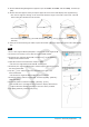
1. Draw a line segment AB and plot point C, which is not on line segment AB.
2. As shown in the nearby screen, draw line segments DE and DC.
3. Select only line segments AB and DE, and then tap u on the toolbar to
display the measurement box.
4. Input 90 into the measurement box and press E.
• This fixes the angle between AB and DE at 90 degrees.
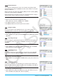
5. Select only line segments DE and DC, and then tap the down arrow next to
the measurement box.
6. Tap the e icon, and then select the check box to the right of the
measurement box.
• This makes line segments DE and DC congruent in length.
7. Select only point E and line segment AB, and then tap [Edit] - [Animate] -
[Add Animation].
8. Select only point D, and then tap [Edit] - [Animate] - [Trace].
• This should cause a parabola to be traced on the display. Note that line
segment AB is the directrix and point C is the focus of the parabola.
9. Tap [Edit], [Animate], and then [Go (once)].