www.axxessid.com Installation & User Guide AX200 & i-BOX Installation & User Guide Axxess Identification Ltd 27-28 Shrivenham Hundred Business Park, Watchfield, Swindon, Wiltshire SN6 8TZ United Kingdom Tel: +44 (0)1793 784002 Fax: +44 (0)1793 784005 Email: info@axxessid.
www.axxessid.com Installation & User Guide Microsoft® is a registered trademark of Microsoft Corporation. Windows™ is a registered trademark of Microsoft Corporation. Document Title: AX200 & I-BOX Installation & User Guide v13.07.07 This document contains proprietary information of Axxess Identification Ltd. Unauthorised reproduction of any portion of this manual without the written authorisation of Axxess Identification Ltd is prohibited. The information in this manual is for informational purposes only.
www.axxessid.com Installation & User Guide License Agreement NOTICE TO USER: THIS SOFTWARE PACKAGE IS A CONTRACT. BY INSTALLING THE SOFTWARE YOU ACCEPT ALL THE TERMS AND CONDITIONS OF THIS AGREEMENT. 1. Use of the Software. You may install and use the software only for the purpose intended. 2. Copyright. You may not duplicate or copy the software or documentation, except that you may make one backup copy of the software. All copies must bear copyright notices contained in the original copy. 3.
www.axxessid.com Installation & User Guide Contents ...................................................................................................................................................1 AX200 Installation .....................................................................................................................8 AX200 Software Setup ............................................................................................................8 TCP/IP Configuration (Fixed IP Address)..
www.axxessid.com Installation & User Guide Photo................................................................................................................................44 Photo ID ...........................................................................................................................44 Add a Photo......................................................................................................................45 Capture Picture from Camera......................................
www.axxessid.com Installation & User Guide E-Mail Unknown Format to Axxess ID ...............................................................................71 DB Maintenance ...................................................................................................................72 Compact Database ...........................................................................................................72 Backup Settings............................................................................
www.axxessid.com Installation & User Guide PDU (Power Distribution Unit) ...............................................................................................93 Details ..............................................................................................................................94 Sensor ................................................................................................................97 Hardware Connection Details......................................................
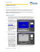
www.axxessid.com Installation & User Guide AX200 Installation This Installation Guide details the initial setup and steps to get the AX200 software operational. For further information and additional features please refer to the AX200 software manual. Complete software installation and TCP/IP configuration must be performed whilst logged into Windows with full Windows Administration rights. AX200 Software Setup 1. Install the AX200 software.
www.axxessid.com Installation & User Guide 9. Click on the ? at the end of the Server IP address. The Server IP address will fill in. On local area networks (LAN) the Device IP address and the Server IP address will match for the first 3 numbers (Segment address) and the last number will be unique to the AX200. 10. Enter a name for the AX200 and an IP address for the device. To ensure that this IP address is not already assigned click on the ? next to the device IP address.
www.axxessid.com Installation & User Guide 12. Click Add. Select the type of reader (with or without PIN) then click next. Enter a suitable name for the door location being added. Then click OK. After a brief period of time the add wizard will be completed. Access point specific settings such as lock times, IN/Out configuration may be set under Access point / Access point. When a new AX100 is added the access point screen will be displayed.
www.axxessid.com Installation & User Guide address. Typically this is set to 255.255.255.0 Click OK or Apply. Click OK to exit the network setup and close the system control panel window. If prompted to reboot or to insert the Windows installation disk please follow the on-screen prompts. IP Definitions Applicable to the AX200 IP Address An IP address is a unique identifier for each controller, PC or other Ethernet device.
www.axxessid.com Installation & User Guide recommended that the segment address is 10.1.1.x Use the subnet mask as 255.255.255.0 and the gateway IP address should be 0.0.0.0 WAN Configuration When working on a wide area network (WAN) all devices that are configured to operate with fixed IP address such as the AX200 controller, will probably have a different segment address. So if the Server (PC) IP address is 10.1.1.15 then the AX200 will require an IP address with the appropriate segment such as 10.1.2.
www.axxessid.com Installation & User Guide Sounder /Beacon for i-BOX (IC-ASB) The sounder /Beacon for the i-BOX connects directly to the i-BOX and will sound the alarm and flash the strobe for a pre-programmed period of time when an alarm condition occurs on the iBOX. Connect the 9 way D connector to the i-BOX. To configure the duration select the environment button in the software. Click on the I-box in the tree menu. Adjust the alarm sounder period time to the desired length of time and click Save.
www.axxessid.com Installation & User Guide AX200 Expander Board Connections Expander Board connections are located at the top-right corner of the AX200 board. Output 4 (associated with door 1) & output 5 (associated with door 2) are activated once the “Door forced/held open alarm” is triggered on the appropriate controller and will stay active until the alarm is cleared either by using a valid card or by using the clear alarm button on the main screen.
www.axxessid.com Installation & User Guide Door forced / held open alarm settings can be accessed through Main Screen • Access Point • (Enable) Door Contact. For more information about these settings please refer to Access Point Configuration • Access Point Settings on this manual. Note: Relay No.3 generates a 1 second pulse through the Access Granted connection block, located at the top of AX200 board.
www.axxessid.
AX200 Installation & User Guide – July 2007 Installation & User Guide www.axxessid.
AX200 Installation & User Guide – July 2007 Installation & User Guide www.axxessid.
www.axxessid.com Installation & User Guide AX200 Software The AX200 software is where all the programming data and cardholder information is entered. It consists of the following: • • • • • • • Cardholder Access Point System Settings Format & Statistics Security Reports Environment The PC is where all the system configuration and data management is stored.
www.axxessid.com Installation & User Guide Please read the License Agreement, to accept the terms select I accept… then click on Next >. The default directory where program files are installed is C:\Program Files\AX200\ If required, click on Change to choose a different folder. Click on Next > to accept the default, or when you’ve entered a different destination folder.
www.axxessid.com Installation & User Guide The AX200 program files will now be installed. The AX200 installation is now complete. Select Finish to exit the setup wizard.
www.axxessid.com Installation & User Guide Some operating systems also require Microsoft Data Access Components to support SQL. This is automatically installed if required. Please follow the on-screen instructions. Starting the AX200 Software Connect your AX200 controller to the PC using the communication cable supplied. Go to Start • All Programs, left click on AX200 Access Control System and it will launch the AX200 software, alternatively double click the AX200 logo from the Windows desktop.
www.axxessid.com Installation & User Guide The AX200’s default user name is 1 and the default password is 1. The user names and passwords are not case sensitive. Enter the default user name and password and select OK. Language Selection Installation and operation of the software can be selected in different languages. Changing the language can be done from the login screen as well as within the program on the main screen, without the need to restart the software or the computer.
www.axxessid.com Installation & User Guide Backup & Restore The AX software has a built-in backup utility. Backups can be done automatically at preset times and days, or manually with network backup support. Backups from older software versions are automatically converted avoiding the need for multiple steps to restore the software. A backup can be restored in one single step. Automatic backups are numbered using the date and time the backup took place.
www.axxessid.com Installation & User Guide Backup time settings window can be reached through the File menu. The default day and time for automatic backup is displayed on the left side of the window. By default, the application will take a backup of your database at 23:59:00 every night. Settings on the right hand side give you more options on how to manage your backup files.
www.axxessid.com Installation & User Guide Email settings could be sent to a specific group of people via Email. You need to specify the time period during which you would like the email to be sent out (Time Zone), the information you want to include (Attachments) and the name of the recipients (Groups). Enter the name and email address of the sender on the left. If you’re using a local server enter the name of your local SNMP server for email.
www.axxessid.com Installation & User Guide Database Integrity Check A mains failure or system crash with an open database normally requires running a separate application to repair the data. All data in the AX200 database is automatically checked on start up and repaired if necessary. At the start-up, the software automatically checks the database version.
www.axxessid.com Installation & User Guide Provide a name for the access point i.e. the location and select OK. Plug & Play Devices The PC communication port is automatically setup and new devices connected will be automatically detected and can be added (or replaced) using the new device wizard, which allows setting up a new controller in seconds. When enabled under system settings, Plug & Play is active at all times and does not require a restart of the application or computer.
www.axxessid.com Installation & User Guide Controller Status & Control Devices connected are highlighted and display the door status in real-time on the main screen. Doors can be controlled directly from the main screen. Commands can only be given to controllers online and functionality is greyed out if the controller is not available online to avoid any uncertainty. Door open Normal mode Door unlocked High security mode Deadlock Clear alarm Opens the door for a set time e.g.
www.axxessid.com Installation & User Guide Door Unlock Mode This feature can be activated from the PC or cards with the “set unlock” feature enabled. Using a card with this feature twice consecutively at the reader will permanently unlock the door. To return to the normal mode, use the card again twice consecutively. Typical applications include reception doors during normal office hours or for goods inward deliveries.
www.axxessid.com Installation & User Guide Force Download & Clear Controller Clear controller deletes the database that has been stored in the controller. Once the controller is cleared, the door becomes permanently unlocked. At this time if a card is presented to the reader, a transaction will appear on the screen saying “Door is unlocked” followed by the cardholder’s name, card number and the door’s name.
www.axxessid.com Installation & User Guide The list on the top shows all the units that have been configured on your PC at some point. This can also be found in Access Point • Device Manager. You can also test the connection between the online units and the PC by pressing the Test Connection button. The graph on the bottom, demonstrates the performance of different elements of your system such as the CPU, hard disk and …..
www.axxessid.com Installation & User Guide field. All system transactions are colour-coded, valid entries are displayed in green, access denied transactions etc in red and system messages in yellow. The number of transactions kept in memory for quick overview on the main screen can be set under “System Settings”. The larger the number, the more memory will be required. Transactions are always stored and can be viewed or printed under “Reports”.
www.axxessid.com Installation & User Guide Note: in order to program the software to print out the who’s in list when the fire alarm goes off go to Display Filters • Printer • Setup and enable the Auto print on fire alarm. Display Filters This screen includes 13 different tabs, however only 4of them are included in the AX200 software. The other 9 features are only available in the AX500 software. The Display Filters tab contains a list of 14 different types of transactions that appear on the main screen.
www.axxessid.com Installation & User Guide Select the appropriate transaction simply by ticking the check box next to it. From the time zone column select the time zone during which you would like the email to be sent out. Selecting “Always Access” would send the email at any time. The attachment menu gives you the ability to specify what information you would like to be included in the email. To add a new attachment click on the Attachment button on the bottom of the screen.
www.axxessid.com Installation & User Guide fields click Save & OK and go back to the email tab. Now you can select the attachment that you just made from the drop-down list. The next drop-down list includes the person or the group of users whom the email will be sent to. To add a new group click Group on the bottom of the screen. To create a new group click on “Add” and enter an appropriate name. Enter the name and the email address of the recipient. When you’re finished click Save & OK.
www.axxessid.com Installation & User Guide The test wizard will guide you through automatic setup of the card formats and a complete hardware and software test. On the Test Wizard screen type in the card number of one of the cards which you would like to test and select Next. Ensure your AX200 controller is still connected to the PC – the Test Wizard will now check and communicate with the controller. If the controller is communicating correctly a green acceptance tick is displayed.
www.axxessid.com Installation & User Guide The Test Wizard will now check and verify the card format, facility code and card number. Select Next to continue. The Test Wizard will now configure the card format, cardholder, and access point and download the data to the controller. Select Next to continue.
www.axxessid.com Installation & User Guide Now the Test Wizard will complete a number of hardware tests – please follow the on-screen prompts.
www.axxessid.com Installation & User Guide Select Next to continue. Once completed, additional cardholders can be added by selecting the cardholder icon or through the cardholder configuration screen. Optional features can be set through the access point configuration.
www.axxessid.com Installation & User Guide Cardholder Cardholder configuration consists of five elements • • • • • Main Settings Other Info Mode Settings Personal Info Vehicle Info Adding new cardholders can be done from the main settings screen. The other tabs are for extra features and additional database fields. Main Settings Card Number Unique card number – maximum 10 digit number. This number excludes the facility and site code number which is defined in card type.
www.axxessid.com Installation & User Guide Imprint Number If the number on the card is not the ‘true’ number in the card, then this printed number can be entered here. Alternatively this field can be used for other data e.g. membership numbers etc. Employment To indicate the type of cardholder, fields can be selected from the drop-down box or entered manually. When entered manually it will ask for confirmation when you save the record and can be selected the next time from the drop-down box.
www.axxessid.com Installation & User Guide downloaded onto the controller. Every day of the week has been divided into the periods of 15 minutes. Red zone is when the card holder will not gain access through the door. If the cardholder presents his/her card during this period the message on the screen will say that the time zone is not active and therefore access will be denied.
www.axxessid.com Installation & User Guide Photo A digital photo can be added in the following formats – JPEG, GIF and BMP. To add a cardholder photograph, click on the Photo button and select the file using the browser. If the controller is used on-line then every time a cardholder presents a card, the transaction including the photo will show on the Main Screen.
www.axxessid.com Installation & User Guide To access the Photo ID window click on the “Photo” button under the “Main Settings” tab in the Cardholder screen. Photo ID window is where you can add a picture or change the template on your card. Add a Photo There are two ways of adding a new photo to your card. You can either import a photo from a file or use a camera. Capture Picture from Camera If there is a camera connected to your PC you can have live picture on your screen.
www.axxessid.com Installation & User Guide Import Picture from File You can also import a photo from a jpg, gif or a bmp file on your PC. Just click on the import button, select the file on your hard disc then click open. Templates To create a new template click Add. By default the company’s logo would be displayed instead of the cardholder’s photo unless you import a picture either from a camera or a file on your PC.
www.axxessid.com Installation & User Guide Card Replacement Wizard Card replacement wizard will substitute the current card with a new one. You can specify which card status you want the current card to change to. After clicking Next the current card will be deactivated. All you have to do now is to enter a new card number.
www.axxessid.com Installation & User Guide Card Diagnostics Card diagnostics gives you a summary of the current cardholder setting details. If a card does not have access to a door, then the diagnostic button is a quick and easy way to see why. After selecting the appropriate door click Next.
www.axxessid.com Installation & User Guide The information on the left is a brief summary of cardholder setting details and the associated access point settings which can also be found under cardholder Configuration • Main Settings & Access Point Configuration • Access Point. Diagnostic summary on the right explains weather or not the current card holder will get access through the selected door. Search Searches can be performed on the cardholder record by clicking with the mouse on the field label.
www.axxessid.com Installation & User Guide <5 1-5 will produce a result of all cards less than 5 will produce a range of cards from 1 to 5 From the search list you can either select the required record or press Escape key (Esc.) to exit. The search facility also allows partial searches e.g. by clicking on the surname field label you can enter the first letter (or more) of the surname and the results will automatically be displayed on screen.
www.axxessid.com Installation & User Guide Card number Imprint number First name Middle name Last name Nickname Initials Employment type Department Job title Access group Card type Card status PIN code Photo up to 10 digits 20 characters – usually the number printed on the card 30 characters maximum 30 characters maximum 30 characters maximum 30 characters maximum 10 characters maximum e.g. contractor, visitor, part-time - unlimited number of characters 50 characters e.g.
www.axxessid.com Installation & User Guide Employer To add a new employer click on the drop down menu. Once the employer list has been opened click Add. You must enter an Employer Name in the Employer Configuration window. Once you’re finished click save and exit. You can edit an existing employer by clicking on the Edit button.
www.axxessid.com Installation & User Guide Mode Settings Individual setting per door and per user for High Security and Latch function • • • • authorised to set Latch function authorised to set High Security mode access granted in High Security mode extended door open time on valid card use Mode settings tab is an important section of cardholder configuration. It allows you to programme a card to have a specific effect when presented to each reader.
www.axxessid.com Installation & User Guide High Security (Hi Sec) If a door is set on high security mode, you need to have a high security card to unlock it. Mode settings section is the place to create a high security card. By default no card has the permission to open a high security door. However you can grant this permission simply by changing the text NO to Yes (by clicking on it) under the Hi Sec column. Extended Door Open Time (Ext’d Door) Activates the Extended Door Release Time function.
www.axxessid.com Installation & User Guide Home phone text field maximum 30 characters Mobile text field maximum 30 characters Email address text field maximum 50 characters Home page text field maximum 50 characters National Insurance No text field maximum 20 characters Payroll text field maximum 20 characters Notes text field maximum 255 characters Vehicle info Contains information about the person’s vehicle. You can choose your car make and model from the appropriate list.
www.axxessid.com Installation & User Guide Access Point Configuration Access Point Settings Access Identity Every device has a unique “Access Identity” and is given a distinctive “Access Point ID” when connected to the PC. Each controller has a serial number and this is used to communicate with the PC. If the identity has been entered manually during a system setup or where controllers are connected using a DTU, then the replace function should be used when the controllers are operational.
www.axxessid.com Installation & User Guide Door Comments This memo field can store additional details regarding the location or any other use e.g. temporarily out of use due to building work Every reader can be programmed as Normal, In Reader and Out Reader. If a reader is set to operate as an In Reader, the card number and the person’s name would appear on the “who’s in list” when the card is presented to it.
www.axxessid.com Installation & User Guide Door Release Time Standard door release time is the amount of time it takes for the door to be locked again, after being opened by a valid card. (Range: 1•255s) If the “Extended door open time” option has been activated in the mode settings of a card; then the door will remain open for the amount of time entered in the Extended field. (Range: 1•255s). It allows individual cardholders to have the door open for a longer period of time e.g.
www.axxessid.com Installation & User Guide Door contact settings are enabled by ticking the Door Contact box. Door Forced Alarm: generates an alarm immediately after the door has been opened by using force. The alarm is cleared automatically as soon as the door has been closed. However the sounder remains active until you select the appropriate reader from the menu on the right hand side of the main screen and press “Clear Alarm”, or present a valid card.
www.axxessid.com Installation & User Guide PIN Timeout: Indicates in seconds, the time required to enter the PIN number before clearing the buffer or sending the data as invalid or incomplete. A longer time might be required for elderly, disabled or specific locations i.e. car parks. High Security activates PIN: The system normally operates in card only mode and changes to card + PIN when a High Security card is used four times at the reader.
www.axxessid.com Installation & User Guide Firmware Version Firmware revision number in AX100 PCB Batch Number Production identity number Serial Number in Batch Serial number to be used with batch number Database Stamp This number is automatically generated and ensures the correct data is automatically downloaded. If another PC is connected, this number is different and a forced download is required since the data held on the PC and the AX100 controller are different.
www.axxessid.com Installation & User Guide Creating a new access group Making a new access group is very easy and quick. All you have to do is to click on the “Add” button and transfer the appropriate doors from the “Controller(s) available” list over to “Controllers in group” list. In order to move an access point across; you can either double click on it or highlight it and press the > button. Clicking on the >> button would transfer all the access points at once.
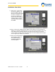
www.axxessid.com Installation & User Guide So if the PC server icon is red open the server configuration window by double clicking on the icon. If the Server IP field is blank or contains a number which is different from the IP address of your PC click on the •? Button. The software will automatically obtain the correct IP address of your PC. When you’re done click OK. The PC server icon should now be blue.
www.axxessid.com Installation & User Guide After pressing Yes, the correct IP address is automatically detected and displayed. This IP address will be recorded in the database as the server IP. If the IP address of the PC does not match with what's been recorded in the database, the software will warn the user at the startup by displaying the following transaction.
www.axxessid.com Installation & User Guide Device Status Indication If a device has been disconnected from the network it goes off-line and is displayed with a red cross on it. If a device icon is red it means the controller is connected to the network but is not programmed to communicate with your PC. In order to configure a device on your PC open the Tcpip Settings window by double clicking on the device icon.
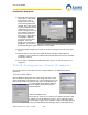
www.axxessid.com Installation & User Guide In the Tcpip settings window, under the Device settings tab; click on “?” in front of the Server IP field (on the bottom) to obtain the server PC IP address. The device IP address is made up of 4 numbers separated by “,” and is located in the top half of the screen. The first three numbers of the device IP address must match the first three numbers of the Server IP address. However the fourth number could be anything between 1 and 254.
www.axxessid.com Installation & User Guide Device Settings Device settings tab mainly provides you with the network settings of the selected unit. Every unit is given a unique name by the application when connected to the net work. You can change this name at any time. To avoid any possible conflicts in the network make sure you don’t choose a duplicate name. The IP address of the server is displayed at the bottom of the page. The correct IP could easily be obtained by clicking on the ? Button.
www.axxessid.com Installation & User Guide Fire alarm This section gives you the ability to unlock all the doors in your building simultaneously by using only one controller. The way it works is that, if the fire alarm is triggered on the current controller all the access points listed in the doors selected list will be opened at once. To enable the settings tick the Enable Fire Alarm box. Doors available list contains all the access point configured on your PC.
www.axxessid.com Installation & User Guide System Settings A continuous check is carried out on the PC’s system resources. These graph bars are located under the system settings menu and indicate the performance of the system. Often systems grow bit by bit and no care is given to memory, hard disk space or CPU usage. This can result in very slow operation or, in the case of lack of hard disk space, a computer crash.
www.axxessid.com Installation & User Guide Test Wizard The test wizard provides an easy and effective way to setup the AX200 system. Together with hardware and software tests, the test wizard enables you to setup the appropriate card format. The card used for testing will have access to all doors with high security and latched (door unlocked) functions enabled. At the end of the wizard, the test report can be printed to a default printer and the test card can be deleted if required.
www.axxessid.com Installation & User Guide Test wizard is also accessible under Tools menu on the main screen. E-Mail Facilities When additional cards need to be re-ordered, it is often difficult to know the type of card, facility code etc. which can result in delays of card supply or the supply of incorrect cards for the system. The send card numbers and facility code, emails all the relevant data to the installer. This feature requires an internet connection.
www.axxessid.com Installation & User Guide DB Maintenance Database maintenance is normally done by the AX200 automatically. If data is corrupted because of an unexpected shutdown of the PC this is repaired automatically when the software is restarted. All erase functions require an override password and are normally never used. After each backup, files are automatically deleted.
www.axxessid.com Installation & User Guide The database can become slow if a large number of additions and deletions of records occur. The compact database function reorganises the database which reduces the database size and improves the speed. Compacting the database is recommended every three months or every 500 cardholder changes. Backup Settings It is strongly recommended to backup the system frequently. This can be done manually or automatically at preset times and days.
www.axxessid.com Installation & User Guide Firmware update functions both manually and automatically. If the automatic option is selected all the units on the network will be upgraded to the latest version of firmware on 11:00 PM at night. Both rabbit FW and I-box FW will be automatically upgraded. If a device already has the latest version of firmware, it will not be affected.
www.axxessid.com Installation & User Guide Hidden functions are only displayed when the Special Functions in the General Settings tab are enabled. These features are for engineering purposes only. That’s why by default these functions are disabled. These functions include: Erase Main Database, Erase Log Database, Erase Event Database, Erase Bug Database and Erase All. Erase All includes all the other erase functions and will replace your current database with a default (blank) one.
www.axxessid.com Installation & User Guide General Settings Maximum PIN Number 1~6 This option sets the maximum number of digits required when using a PIN code. If a PIN only is being used and the PIN code is less than the number of digits set under this setting, the # key is required to complete the action. Number of Lines in Screen This is the number of transactions kept in active memory, allowing the user to see them instantly on the main screen.
www.axxessid.com Installation & User Guide Link Alive Retry Times The AX200 and the I-box units send a link alive message to the PC every 5 seconds to confirm that the communication is stable. If the PC doesn’t receive this message it assumes that the unit has gone off-line. This option specifies the number times that the PC will attempt to get a link alive message before the “PC Off-line” transaction appears on the main screen.
www.axxessid.com Installation & User Guide Select COM Port The AX200 software on start-up will automatically scan COM ports 1 to 4, and if found, display the port found. Consequent start-up of the AX200 software will look at the port found address only. By selecting auto-detect, the software will scan all ports and find the appropriate COM port. Manually ports 1 to 16 can be selected if required. Baud rate and parity settings are automatically configured. The default setting is “Disable”.
www.axxessid.com Installation & User Guide Multiple Formats – The AX200 software allows that each cardholder has a unique format. If selected, then a card type (this includes format and facility code) should be selected for each cardholder. Single Format – Normally cards are of the same format and facility code. If cards of the same technology/manufacturer are used from other systems then multiple formats can be used. Single format is the default setting.
www.axxessid.com Installation & User Guide Card Type Information The AX200 supports up to 4,000 different card formats and facility codes. The format and facility code combined is called a card type. Format is the number of bits programmed in a card and the location of parity checks. E.g. 26 bits O F F F F F F F F C C C C C C C C C C C C C C C C E odd parity 1 to 13 facility code card number even parity 14 to 26 The first and last bit check that the data received is correct.
www.axxessid.com Installation & User Guide Most card manufacturers have their own specific format, providing a higher security than the ‘open standard’, which is not as secure. The default facility code is 50 bit card format, providing the highest level of card number security. Card Matching The AX200 supports a number of well known formats. Enter the card number and if known, the facility code. Present the card to the reader (systems should be online). If know, it will display the possible format.
www.axxessid.com Installation & User Guide Individual passwords can be issued to different users with different rights to view and edit. Passwords are not case sensitive. The default user 1 cannot be deleted however the password can be changed. Adding a New User To add a new user, select New, enter the user name, password and confirm the user password. You are asked to select an existing group authorisation or alternatively you can setup a new group by selecting the Group Authorisation tab.
www.axxessid.com Installation & User Guide Select the Group Authorisation tab, select New, type in the new Group Name. Double click on the current group access permission symbols to enable or disable the permissions. Access enabled Access disabled Select save. Report The AX series has a built in report generator which allows full or filtered information to be viewed on screen or printed. Colour printers are supported and give the benefit of alarm messages printed in red.
www.axxessid.com Installation & User Guide Powerful reports are easily obtained entering selection criteria. The report will only include the information obtained up to the last backup.
www.axxessid.com Installation & User Guide Cardholder Details Displays all the information in the cardholder screen in details along with the picture of the card holder. Log File All the system transactions from the online controllers are stored, including all operator actions. Cardholder, system changes and operator commands are all stored in the log file with date, time and the type of transaction. eg 12:00 05/12/2002 card 52 added. The log file can be viewed or printed using selection criteria e.g.
www.axxessid.com Installation & User Guide Work Spell An exclusive feature in the AX200 application gives you the possibility to calculate the total number of hours which an individual or a group of cardholders have spent inside the building. You can search a cardholder by their name or card number and workout the number of hours they have spent in the building, during a specific period of time.
www.axxessid.com Installation & User Guide Printing This will provide a selection of reports, all the data is sorted on the screen. To print, select the print icon or select the envelope icon to export the data from the report. Reports can be exported to a number of spreadsheet and word processor formats as well as ODBC and common data interchange formats. This makes the distribution of information easier. The export process requires you to specify a format and a destination.
www.axxessid.com Installation & User Guide All operation commands/database or system changes are stored and can be previewed in Reports. i - BOX A new product introduced along with the AX200 software; i -BOX provides both access control security and environmental monitoring. Each i-BOX includes a built in temperature, humidity, light and voltage sensor with 14 ports for plug and play connections of additional smart sensors, together with 2 access control ports.
www.axxessid.com Installation & User Guide Dust Particle Sensor Monitors the concentration of dust particles in the air flow The picture bellow gives a brief description of the ports and LEDs on the i-BOX. Environment An essential part of the AX200 software which is exclusive to the i-BOX. Environment screen contains settings and configurations for the i-BOX activities.
www.axxessid.com Installation & User Guide i- BOX Parameters The diagram on the left shows all the i-box units configured on your PC. On-line units are displayed in green. Clicking on + will display all the sensors connected to that i-box. Other than the first two sensors which are already in the i-box, there are 14 empty ports for smart sensors to be plugged in. Once a new sensor is plugged in, a new device wizard will be opened and you can easily configure your sensor.
www.axxessid.com Installation & User Guide Sensor Name is specified by the user and can be changed at any time. Port No displays the number of the port which the sensor is connected to (1•14). In the case of a built-in sensor like Temperature/ Humidity, it shows Internal. To enable a sensor tick the check box and click the save button on the bottom of the page. Once the sensor is enabled it will start taking readings. Read frequency specifies how often you want the sensor to take a reading.
www.axxessid.com Installation & User Guide When a door is opened there might be a dramatic change in the sensor readings (especially temperature and light sensors), which may results in generating a false alarm. By enabling this feature the application will ignore the alarm generated by that sensor once the door has been opened. Shunt alarm on delay In the same way, when the door is closed the reading will go back to its original status quickly which may cause in generating an alarm.
www.axxessid.com Installation & User Guide The default maximum value is 5 seconds. This means, when the I-box sends a transaction to the PC it will wait for a response from the PC. If it does not receive any response it will wait for 5 seconds before sending another message. This number is doubled with every try, until it reaches 80 seconds (Minimum Timeout).
www.axxessid.com Installation & User Guide High and low limits could be defined for both voltage and current. Once the reading exceeds these limits it will trigger an alarm and the appropriate transaction will appear on the main screen, providing the sensor’s type, alarm description, i-BOX name and sensor ID. Details The status of the sockets is displayed on the left hand side. Each status has a unique colour.
www.axxessid.com Installation & User Guide Normal Current: shows the normal amount of current consumed by each device. This value is determined by the user and is merely for user’s information and has no effect on the operation of the PDU. Permit to work & Date/Time: the last two columns are for entering a brief explanation in case of a socket being switched of by the user. To switch off a socket remotely click on the ON/OFF buttons on the left hand side.
www.axxessid.com Installation & User Guide Pressing the End delay button will terminate any delay time and all the sockets in the unit will be switched on. Reset Power button will bring the value of total power back to zero. Voltage, current and the power readings are displayed on the LCD screen on the PDU. If you press button No.4 you’ll be able to view the Serial Number. Button No. 5 will display the channel status for all the sockets.
www.axxessid.com Installation & User Guide Sensor Redetec sensors are Input/output modules specifically designed to be used with Redetec units to provide the ultimate cabinet protection. Redetec is a self-contained automatic fire extinguishing unit, which can be used in many industry sectors. Like all the other plug & play smart sensors, redetect sensor is connected to the I-box using a standard sensor cable only. The unit takes 2 inputs, Faults & Fire.
www.axxessid.com Installation & User Guide Sensor’s specifications are displayed at the top of the screen. You could specify how frequent you would like the sensor to take readings and how often you’d like the readings to be reported. All the reported and unreported data will be stored in the log file and can be accessed via the report section. If the Alarm on Fault/Fire is ticked, once there is a fire or fault in the unit, an alarm transaction will be generated and displayed on he main screen.
www.axxessid.com Installation & User Guide Note: if the Redetec sensor goes off line for any reason, it will lose control over the Redetec unit. This means if the unit has been isolated by the sensor, it will come out of isolate once the sensor is disconnected. Therefore we strongly recommend using the key switch for isolation before starting any maintenance work. PIR PIR sensors have been designed to detect movements in an adjustable range of 5 to 15 meters.
www.axxessid.
www.axxessid.com Installation & User Guide Dust Particle Sensor Dust sensor has been designed to detect the level of dust particles in the air. The air is sucked in through the air inlet on the side and released through the outlet on the top. Once the air comes in contact with the sensor the level of dust particles is measured and reported through the software. Please note that the dust sensor must be fitted sideways and the air inlet and outlet should not be blocked.
www.axxessid.com Installation & User Guide Mains Present Sensor Mains Present sensor is directly connected to the i-BOX through one of the 14 ports on the back using a standard sensor cable. Once the sensor has been detected by the i-BOX, a new device wizard will appear on the screen. Follow the on-screen prompts to add the sensor to the database. Use the cable ties on the sensor to strap the sensor onto the mains cable.
www.axxessid.com Installation & User Guide from the sensor, then add one to whatever the value of Gain is at that moment. For example if the sensor starts detecting the mains at Gain = 33, then the suitable sensitivity would be Gain = 34. If “Alarm on off” is ticked in the sensor’s settings; once the mains in the cable is lost; an alarm transaction will appear on the main screen stating the date & time and the type of the alarm. All the alarms and routine readings can be observed in the Reports section.
www.axxessid.com Installation & User Guide By pressing OK, database changes are automatically downloaded into the DTU. A list of controllers requiring a download can be printed using the reporting function. Once the data has been downloaded into the DTU, disconnect and plug the unit into the AX100 controller directly (no cable or power supply is required). The data is now automatically transferred into the controller.
www.axxessid.com Installation & User Guide 9 or 25 Way to COM1 or COM2 Power Supply RJ45 Connector Upload data to the DTUDTU Download data to AX100 DTU The DTU is fully automatic without any buttons or other complicated things to do. Connect the DTU to the PC and once the information is loaded walk to each door and insert the DTU in the 15 way connector. The DTU will automatically know which information has to be downloaded.
www.axxessid.com Installation & User Guide New doors can be added by simply plugging the DTU into the controller and returning back to the PC. This will automatically start the new device wizard, which allows you to add the new controller. There is no need to pre-program the controller at the PC first; all settings are handled by the DTU. Note: - the DTU must be in the current controller list however it does not need to be active for this function to work.
www.axxessid.com Installation & User Guide 7 DTU Operation 1. 2. 3. 4. 5. 6. 7. 8. 9. 10. 11. 12. 13. 14. 15. 16. Start the AX200 software on the PC. Connect the DTU to the serial port on the PC. The auto detect hardware device wizard will start within 10 seconds. Follow the on-screen prompts to add the DTU into the software. Remove the DTU from the PC and plug into a controller. Wait 10 seconds Remove the DTU from the controller and plug it back into the PC.
www.axxessid.com Installation & User Guide Clear DTU This command can be found on the main screen toolbar. If the DTU has been used for testing purposes with other controllers not belonging to the customers’ site, then the DTU will inform you that there is a new device, until you clear the DTU. Just highlight the DTU in the current controllers list on the main screen. Now click on tools on the toolbar and select Clear DTU.
www.axxessid.com Installation & User Guide The AX200 has now been removed from your PC. Anti-Virus Sometimes the activities carried out by the AX200 software can be disrupted either by the firewall or the antivirus software which is protecting your PC. This section is intended to provide you with the solutions to some of the problems caused by the most popular antivirus packages.
www.axxessid.com Installation & User Guide In order to change the antivirus settings, perform the following steps (On the PC that the AX200 is running): I. II. III. IV. Select virus scan console from the system tray. Select access protection Select the Rule "Prevent mass mail worms from sending email Port 25" and click edit. Add axid.exe (in lower case) to the excluded process's - note if this is not enabled then enable it, if more than one process is in the list each process is separated with a comma. V.
www.axxessid.com Installation & User Guide Readers Fingerprint Reader The Verid + fingerprint verification units are standalone devices, designed to provide access control system with instant improved security, or to act as a means of identity verification in a wide range of different applications. The Verid + fingerprint verification units are available as 3 variants: 1. Verid +, 2.Verid + PIN and 3.Verid + PROX.
www.axxessid.com Installation & User Guide Connection Diagram AX100 to Verid+ Power Supply +12VDC + - Lock Relay Puissa nce Power In/ +12v 0v 0v D0 +12V Red 0 V LED D1 Door C'tct C 12v White Clock (D1) Data (D0) Green J6 Power Output J7 Blue + Yellow Black RX TX 0V N /A Lecteur Reader wiring connections shown are for standard AX readers. Les raccordements de câblage de lecteur montrés sont pour les lecteurs standard AX.
www.axxessid.com Installation & User Guide up. Note that the card number should be smaller than 65535 otherwise the card number that appears on the screen would not be correct. To program Verid+ to expect Wiegand 2601 format you need to use Verid + software (Win 95, 98) provided with the unit. Use the provided cable to connect the unit to the serial port on the back of the PC. Then open the software and click on Connect in the Connection menu. To enter the Configuration mode open the Mode menu.
www.axxessid.com Installation & User Guide You need to add this format through the New Format Wizard. Getting Started Quickly 1. Do the connections according to the table provided in the first page. 2. Install the Verid software provided with the unit and connect the unit to the serial port on the back of the PC. 3. Enter the configuration mode (password: Config) 4. Make sure that the database is empty. (If the database is empty the unit will automatically enter the super user mode at the start up.
www.axxessid.com Installation & User Guide Proximity Readers Honeywell proximity readers have been designed to be installed for use with access control systems. The following instructions outline the connections between the reader and the AX200 access control system as well as the software configurations that need to be carried out in order to make the system ready to operate. How to connect the reader to the host The reader is supplied with an 18-inch pigtail, having a 6-conductor cable.
www.axxessid.com Installation & User Guide 5. The most common card formats associated with Honeywell proximity readers are Honeywell 1 & 2 which are included in the default database. 6. If the format displayed on the screen is correct, press New Format Wizard. 7. Follow the on-screen prompts to add the new card format. 8. Once the correct card format is added, go to the cardholder screen and add your new card and choose the correct card type. 9.
www.axxessid.com Installation & User Guide AXM Readers The AXM magstripe readers provide high performance and reliability for high security access control. AXM readers are completely weatherproof and suitable for in-door and out-door applications. Output Type • Wiegand 50 bit (Type 5) Other output formats available for most OEM applications Magstripe cards supplied by Axxess Identification are encoded in order to work with 7¯7 format.
www.axxessid.com Installation & User Guide Proximity Request to Exit The Proximity REX detects the hand within the range of approximately 5cm. Once the hand has been detected, the relay goes off and closes the connection between the relay board and the request to exit terminal on the AX100 controller. The Proximity REX acts exactly like the REX Button and once the request to exit has been granted, the appropriate transaction appears on the main screen stating the time and the name of the access point.