
Owner manual


IOM-DA8/92
pressure is less than 50% of the Diaphragm Proof
Rating (See table below) before shutting off the
process fl uid supply pressure. If the regulator is
specifi ed with a fully supported diaphragm, then
the diaphragm will withstand a loading pressure
equal to the Diaphragm Proof Rating for the fully
supported diaphragm.
9. Downstream Sensing Installation Considerations
– Internal or External Sensing:
a. The regulator may be installed with internal or
external sensing. Unless otherwise specifi ed,
the regulator is supplied by factory with internal
sensing. The regulator may be con vert ed in
the fi eld to external sensing (see Section VII
Maintenance, Paragraph H).
b. Reference DAG-TB, Table DAG-11 for recom-
mendations for applying external pressure
sensing.
c. For internal sensing, no external line is used.
For external sensing, use an external control
line. The line is connected from the port (1/4"
NPT) on the side of the body di a phragm fl ange
to an upstream pressure tap. The pressure
tap should be located a minimum of 10 pipe
diameters upstream of the regulator. It is
recommended that the upstream pressure
tap be located close to the point of use to
minimize the adverse affect of variable line
losses. A tubing outer diameter of 0.25 inch
is adequate for short sensing lines (less than
4 feet). Use 3/8" tubing or 1/4" Sch 40 pipe
for sensing lines of 5 to 50 feet.
d. For condensable vapors (i.e. steam) slope
the external sensing line downward 2 to 5
de grees to upstream piping to prevent water
pock ets, which allows the diaphragm chamber
to always be self draining. The external sens-
ing line may be sloped upward for liquids or
gases. (i.e., noncondensable fl uids)
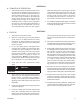
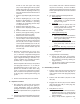
Recommended Piping Schematic for
Differential Back Pressure Station
CAUTION
The proof test pressure must not exceed the
diaphragm and body rating for the regulator.
A hydrostatic or pneumatic proof test is allowable un-
der the following conditions for the standard diaphragm
construction: Uniformly pressurize the valve body inlet,
valve body outlet, and loading chamber to the lesser of
the Diaphragm Proof Rating or 1.5 times the Inlet Pres-
sure Rating shown on the nameplate. For example, a 1"
DA8 with Cast Iron Body and Spring Chamber, Neoprene
Diaphragm (BC) has an Inlet Pressure Rating of 400 psig
CWP. The lesser pressure of 1.5X 400 psig = 600 psig
and the BC diaphragm proof rating of 750 psig is 600
psig. Therefore, uniformly pressurizing the DA8 to 600
psig is allowable. Take care to uniformly depressurize at
end of test.
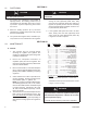
TABLE 1 – DIAPHRAGM PROOF RATING IN PSIG (BARG)
Diaphragm Material
Body Sizes – inch (mm)
1/2" - 2" (DN15 - 50) 2-1/2" - 4" (DN65 - 100)
Standard Diaphragm
Construction
OPT-81 Full
Diaphragm Support
Standard Diaphragm
Construction
OPT-81 Full
Diaphragm Support
BC, EPR 750 (51.7) 1200 (82.7) 450 (31.0) 800 (55.2)
HK, NBR, HK+TFE 300 (20.7) 1200 (82.7) 225 (15.5) 600 (41.4)
FK 500 (34.5) 1200 (82.7) 225 (15.5) 600 (41.4)
Elastomeric TFE 125 (8.6) 125 (8.6) 125 (8.6) 125 (8.6)
17-7 PH SST 500 (34.5) 1500 (103) N/A N/A
Be-Cu 300 (20.7) 750 (51.7) N/A N/A
302 SST 350 (24.1) 800 (55.2) N/A N/A
Inconel 718 500 (34.5) 1500 (103) N/A N/A