
User's Manual

so that they can read the actual non-default values and set them accordingly.
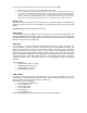
1. Obtain a RJ-11, 6-pin connector and a small length of CAT 5 cable.
2. Pin-out all 6-pins according the following diagram and then short (i.e. solder) together pins 4 and 6
on the other end. Remaining wires should not be connected to anything. Insert “default plug” in the
GPS sync port of the module and apply power to the module via its Ethernet cable. When the
module is booted up (power applied) it will be in default mode where the IP address will be
169.254.1.1 and the passwords will be blank. All other configurations will have been preserved.
EVENT LOG
This page contains information that is recorded from the subscriber module for troubleshooting
purposes. Please make note of the information that is gathered here when calling for technical
support.
Clear Event Log: this button will clear the event log.
LUID SELECT
This web page connects to a registered unit over the RF link, to view its internal web pages. The
Sessions webpage determines which LUID corresponds to a specific unit. Enter the LUID in the
field displayed and then click “Change LUID” to set the parameter. Click “View Current Subscriber
Modem” to access the unit with that LUID.
LINK TEST
The Link Test is a test for measuring the throughput and efficiency of the RF link between two
Cyclone modules. To perform a link test enter a number into the field labeled “Duration”. The
duration is the number of seconds the RF link will be tested. Start the link test by clicking the
“Start Test” button. The test will now run for the set duration. If the web page is not set to
automatically refresh, click the “Refresh Display” button to see the results. For a Cyclone System
link to be considered acceptable it is necessary for the efficiencies of the link test to be greater
than 90% in both the uplink and downlink direction. It is recommended that when a new link is
installed that a link test be executed to ensure that the efficiencies are within recommended
guidelines.
The key fields are:
• Downlink RATE, bits per second
• Uplink RATE, bits per second
• Downlink Efficiency, percent
• Uplink Efficiency, percent
TIME & DATE
This web page is utilized to set the time and date of the access point module when it is not
connected to a Cluster Management Module (CMM). The time and date would need to be set
every time there is a power cycle. The format for the entry is:
Time: hh:mm:ss Date: mm/dd/yyyy
• hh: two digit hour in military time
• mm: two digit minute
• ss: two digit second
• mm: two digit month
• dd: two digit day
• yyyy: four digit year
Enter in the appropriate information and click the Set Time and Date button.