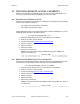
Operations Guide Release 8 28 MAINTAINING YOUR CYCLONE SOFTWARE Cyclone provides release compatibility information and caveats about each release. 28.1 HISTORY OF SYSTEM SOFTWARE UPGRADES 28.1.1 Cyclone Release 8 Features Cyclone Release 8 introduces the following new features: 28.1.
Operations Guide Release 8 28.4 TYPICAL UPGRADE PROCESS In a typical upgrade process, proceed as follows: 1. Visit the software page of the Cyclone web site. 2. Read the compatibility information and any caveats that Cyclone associates with the release. 3. Read the software release notes from the web site. 4. On the basis of these, decide whether the release is appropriate for your network. 5. Download the software release and associated files. 6. Use CNUT to manage the upgrade across your network. 28.4.
Operations Guide Release 8 29 REBRANDING MODULE INTERFACE SCREENS Distinctive fonts indicate literal user input. variable user input. literal system responses. variable system responses. The interface screens on each module display the Cyclone or Cyclone Advantage logo. These logos can be replaced with other logos using Procedure 42. The logo is a hyperlink and clicking on it takes the user to the Cyclone web site.
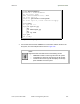
Operations Guide Release 8 > ftp ModuleIPAddress Connected to ModuleIPAddress 220 FTP server ready Name (ModuleIPAddress:none): root 331 Guest login ok Password: 230 Guest login ok, access restrictions apply. ftp> binary 200 Type set to I ftp> put Cyclone.jpg OR put advantaged.jpg OR put top.html ftp> quit 221 Goodbye Figure 165: Example ftp session to transfer custom logo file 3.
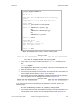
Operations Guide Release 8 >telnet ModuleIPAddress /---------\ C A N O P Y Last Mile Gear Broadband Wireless Technology Center (Copyright 2001, 2002 Last Mile Gear Inc.) Login: root Password: Telnet +> addwebfile Cyclone.jpg OR addwebfile advantaged.jpg OR addwebfile top.html Telnet +> lsweb Flash Web files /Cyclone.
Operations Guide Release 8 below. >telnet ModuleIPAddress /---------\ C A N O P Y Last Mile Gear Broadband Wireless Technology Center (Copyright 2001, 2002 Last Mile Gear Inc.) Login: root Password: Telnet +> lsweb Flash Web files Cyclone.
Operations Guide Release 8 30 TOGGLING REMOTE ACCESS CAPABILITY Based on your priorities for additional security and ease of network administration, you can deny or permit remote access individually to any AP, SM, or BH. 30.1 DENYING ALL REMOTE ACCESS Wherever the No Remote Access feature is enabled by the following procedure, physical access to the module is required for • any change in the configuration of the module. • any software upgrade in the module.
Operations Guide Release 8 31 SETTING UP A PROTOCOL ANALYZER ON YOUR CYCLONE NETWORK Selection of protocol analyzer software and location for a protocol analyzer depend on both the network topology and the type of traffic to capture. However, the examples in this section are based on free-of-charge Ethereal software, which is available at http://ethereal.com/.
Operations Guide Release 8 31.2 ANALYZING TRAFFIC AT AN AP OR BH WITH NO CMM The IP address of the protocol analyzer laptop computer must match the IP addressing scheme of the AP/BH. If the router is configured to be a DHCP server, then configure the laptop computer to automatically obtain an address. If DHCP is not enabled, then ensure that the laptop computer is configured with a static IP address in the same subnet as the AP/BH.
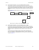
Operations Guide Release 8 CMM 8 7 6 5 4 3 2 1 AP/BH 111 J1 to Radio J2 Ethernet to Switch Sniffer Laptop 8 7 6 5 4 3 2 1 Ethernet Switch HUB Router Figure 170: Protocol analysis at AP or BH connected to a CMM 31.4 EXAMPLE OF A PROTOCOL ANALYZER SETUP FOR AN SM The following is an example of a network protocol analyzer setup using Ethereal® software to capture traffic at the SM level.
Operations Guide Release 8 Figure 171: IP tab of SM with NAT disabled and local accessibility Procedure 47: Setting up a protocol analyzer 1. Note the IP configuration of the SM. 2. Browse to StartÆMy Network PlacesÆNetwork and Dialup Connections. 3. For Local Area Connection, select Properties. RESULT: The Local Area Connections Properties window opens, as shown in Figure 172.
Operations Guide Release 8 Figure 172: Local Area Connection Properties window 4. Select Internet Protocol (TCP/IP). 5. Click the Properties button. RESULT: The Internet Protocol (TCP/IP) Properties window opens, as shown in Figure 173.
Operations Guide Release 8 6. Unless you have a static IP address configured on the SM, select Obtain an IP address automatically for the protocol analyzer laptop computer, as shown in Figure 173. 7. If you have configured a static IP address on the SM, then a. select Use the following IP address. b. enter an IP address that is in the same subnet as the SM. 8. Click OK. 9. Open your web browser. 10. Enter the IP address of the SM.
Operations Guide Release 8 15. Ensure that the Interface field reflects the network interface card (NIC) that is used on the protocol analyzer laptop computer. NOTE: Although you can select filters based on specific types of traffic, all values are defaults in this example. 16. If you wish to select filters, select them now. 17. Click OK. RESULT: The Ethereal Capture window opens, as shown in Figure 175.
Operations Guide Release 8 Figure 176: - Ethereal window, Packet 1 selected This window has three panes: • The top pane provides a sequenced summary of the packets captured and includes SRC/DEST address and type of protocol. What you select in this pane determines the additional information that is displayed in the lower two panes. • The lower two panes facilitate drill-down into the packet that you selected in the top pane.
Operations Guide Release 8 Figure 177: - Ethereal window, Packet 14 selected In this second example, Packet 14 (protocol type HTTP) is selected in the top pane. The two lower panes provide further details about Packet 14.
Operations Guide Release 8 32 TROUBLESHOOTING 32.1 GENERAL PLANNING FOR TROUBLESHOOTING Effective troubleshooting depends in part on measures that you take before you experience trouble in your network. Cyclone recommends the following measures for each site: 1. Identify troubleshooting tools that are available at your site (such as a protocol analyzer). 2. Identify commands and other sources that can capture baseline data for the site.
Operations Guide Release 8 • researching Event Logs of the involved equipment. (See Interpreting Messages in the Event Log on Page 416.) • answering the questions listed in the following section. • reversing the last previous corrective attempt before proceeding to the next. • performing only one corrective attempt at a time. 32.3 QUESTIONS TO HELP ISOLATE THE PROBLEM When a problem occurs, attempt to answer the following questions: 1.
Operations Guide Release 8 • Module Does Not Establish Ethernet Connectivity on Page 477 • Module Does Not Power Up on Page 478 • Power Supply Does Not Produce Power on Page 478 • CMM2 Does Not Power Up on Page 479 • CMM2 Does Not Pass Proper GPS Sync to Connected Modules on Page 479 32.5 PROCEDURES FOR TROUBLESHOOTING 32.5.1 Module Has Lost or Does Not Establish Connectivity To troubleshoot a loss of connectivity, perform the following steps. Procedure 48: Troubleshooting loss of connectivity 1.
Operations Guide Release 8 h. access the Link Capacity Test tab in the Tools page of the module. i. perform a link test. (See Procedure 40: Performing a Link Capacity Test on Page 439.) j. verify that the link test results show efficiency greater than 90% in both the uplink and downlink (except as described under Comparing Efficiency in 1X Operation to Efficiency in 2X Operation on Page 135). k. execute ping. l. verify that no packet loss was experienced. m.
Operations Guide Release 8 Figure 178: NAT Table tab of SM, example b. verify that the correct NAT translations are listed. RESULT: NAT is eliminated as a possible cause if these translations are correct. 5. If this SM is configured for NAT with DHCP, then at the SM a. execute ipconfig. b. verify that the PC has an assigned IP address. c. if the PC does not have an assigned IP address, then • enter ipconfig /release “Adapter Name”. • enter ipconfig /renew “Adapter Name”. • reboot the PC.
Operations Guide Release 8 Figure 179: NAT DHCP Statistics tab of SM, example • verify that DHCP is operating as configured. 6. After connectivity has been re-established, reinstall network elements and variables that you removed in Step 1. end of procedure 32.5.3 SM Does Not Register to an AP To troubleshoot an SM failing to register to an AP, perform the following steps. Procedure 50: Troubleshooting SM failing to register to an AP 1. Access the Radio tab in the Configuration page of the SM. 2.
Operations Guide Release 8 7. In the AP, verify that the Max Range parameter is set to a distance slightly greater than the distance between the AP and the furthest SM that must register to this AP. 8. Verify that a clear line of sight exists between the AP and the SM, and that no obstruction significantly penetrates the Fresnel zone of the attempted link. If these conditions are not established, then verify that the AP and SM are 900-MHz modules in close proximity to each other. 9.
Operations Guide Release 8 12. Power cycle the BHS. RESULT: Approximately 25 seconds after the power cycle, the green LED labeled LNK should light to indicate that the link has been established. If the orange LED labeled SYN is lit instead, then the BHS is in Alignment mode because the BHS failed to establish the link. In this latter case, and if the BHS has encountered no customer-inflicted damage, then request an RMA for the BHS. end of procedure 32.5.
Operations Guide Release 8 3. If these messages are present, check the Event Log tab of another SM that is registered to the same AP for messages of the same type. 4. If the Event Log of this second SM does not contain these messages, then the fault is isolated to the first SM. 5. If the Event Log page of this second SM contains these messages, access the GPS Status page of the AP. 6.
Operations Guide Release 8 32.5.7 Module Does Not Power Up To troubleshoot the failure of a module to power up, perform the following steps. Procedure 54: Troubleshooting failure to power up 1. Verify that the connector crimps on the Ethernet cable are not loose. 2. Verify that the Ethernet cable is not damaged. 3. Verify that the cable is wired and pinned out according to the specifications provided under Wiring Connectors on Page 182. 4.
Operations Guide Release 8 3. Verify that the cable is wired and pinned out according to the specifications provided under Wiring Connectors on Page 182. 4. Connect the power supply to a known good Cyclone module via a known good Ethernet cable. 5. Attempt to power up the known good module. 6. If the known good module fails to power up, request an RMA for the power supply. end of procedure 32.5.9 CMM2 Does Not Power Up To troubleshoot a malfunctioning CMM2, perform the following steps.
Operations Guide Release 8 5. If these efforts fail to resolve the problem, then request an RMA for the CMM2. end of procedure 32.5.11 Module Software Cannot be Upgraded If your attempt to upgrade the software of a module fails, perform the following steps. Procedure 58: Troubleshooting an unsuccessful software upgrade 1. Download the latest issue of the target release and the associated release notes. 2. Compare the files used in the failed attempt to the newly downloaded software. 3.
Operations Guide Release 8 33 OBTAINING TECHNICAL SUPPORT NOTE: The contact information for Cyclone Technical Support staff is included at the end of this section (on Page 485). However, in most cases, you should follow the procedure of this section before you contact them. To get information or assistance as soon as possible for problems that you encounter, use the following sequence of actions: 1.
Operations Guide Release 8 Table 65: Basic site information for technical support Call Log Number: Company: Location: Problem Type: Site Contact: Site Phone: Call Severity (Select One): Open Date: Close Date: Product Types Involved: (ID the product type) 2400 SM/AP/BHM/BHS 5200 ER /BHM/BHS 5200 SM/AP/BHM/BHS 5700 SM/AP/BHM/BHS 1008CK 300SS ACPS110 MAC Addresses: IP Addresses: Software Releases: Boot Versions: FPGA Versions: Authentication ?: Yes/No Type: Is the customer using shielded cabl
Operations Guide Release 8 Link Distance: Network Scenario for this issue: (ID those that apply) Reflectors in use: Yes/No dBm= Jitter= SM to Subscriber PC Yes/No SM to AP (Point to Multipoint) Yes/No BHM to BHS (Point to Point) Yes/No 20Meg or 10Meg backhaul Yes/No Problem Description: NAT/DHCP Scenario: NAT Disabled Yes/No NAT with DHCP Client and DHCP Server Yes/No NAT with DHCP Client Yes/No NAT with DHCP Server Yes/No NAT with no DHCP Yes/No New Install: Yes/No NAT/DHCP Scenario: NAT Disabled
Operations Guide Release 8 • IP address: • Downlink/uplink ratio: • Max range: • Bridge entry timeout: • Number of subscribers: • Method of synchronization: 14. If you selected Figure 29 a. Indicate how many APs are in each cluster. b. Indicate how many AP clusters are deployed (and what types). c. Indicate how many BH links are configured. d. Include the IP addresses. e. Indicate the frequency for each sector. f. Indicate the type of synchronization. g.
Operations Guide Release 8 18. Capture screens from the following web pages of affected modules: • Home page Status tabs as files SM/AP/BHM/BHS_StatusTabname.gif • Configuration page tabs as files SM/AP/BHM/BHS_ConfigTabname.gif • Home page Event Log as file SM/AP/BHM/BHS_Events.gif • Tools page Link Capacity Test tab (with link test results) as file SM/AP/BHM/BHS_LinkTST.gif • Statistics page Radio tab as file SM/AP/BHM/BHS_RFstats.gif 19.
Operations Guide Release 8 34 GETTING WARRANTY ASSISTANCE For warranty assistance, contact your reseller or distributor for the process.
Reference Information Release 8 REFERENCE INFORMATION Issue 2, November 2007 Draft 5 for Regulatory Review 489
Reference Information Release 8 35 ADMINISTERING MODULES THROUGH TELNET INTERFACE In the telnet administrative interface to a module, the Cyclone platform supports the commands defined in Table 66. Many of these are not needed with CNUT. Table 66: Supported telnet commands for module administration Command System help Definition Notes addwebfile Add a custom web file Syntax: addwebfile filename. Copies the custom web file filename to non-volatile memory.
Reference Information Release 8 Command ping System help Definition Send ICMP ECHO_REQUEST packets to network hosts Notes Syntax: ping IPaddress. Sends an ICMP ECHO_REQUEST to IPaddress and waits for a response. If a response is received, the system returns IPaddress is alive. If no response is received, the system returns no answer from IPaddress. reset Reboot the unit Syntax: reset. Forces the module to perform a hard (FPGA and CPU) module reset. (See fpga_conf.
Reference Information Release 8 36 REGULATORY AND LEGAL NOTICES 36.1 IMPORTANT NOTE ON MODIFICATIONS Intentional or unintentional changes or modifications to the equipment must not be made unless under the express consent of the party responsible for compliance. Any such modifications could void the user’s authority to operate the equipment and will void the manufacturer’s warranty. 36.2 36.2.1 NATIONAL AND REGIONAL REGULATORY NOTICES U.S.
Reference Information Release 8 Table 67: US FCC IDs and Industry Canada Certification Numbers and Covered Configurations FCC ID Industry Canada Cert Number Frequencies Module Families Antenna or Reflector ABZ89FC5809 109W-9000 8 MHz channels, centered on 906924 MHz in 1 MHz increments (within the 902-928 MHz ISM band) 900 SM, AP 12 dBi Cyclone integrated antenna 24 dBm (250 mW) 10 dBi Maxrad Model # Z1681, flat panel 26 dBm (400 mW) 10 dBi Mars Model # MAIS91-T2, flat panel 26 dBm (400 mW)
Reference Information Release 8 FCC ID --- ABZ89FC5804 ABZ89FT7629 36.2.2 Industry Canada Cert Number Frequencies Module Families Antenna or Reflector Maximum Transmitter Output Power 109W-5400 20 MHz channels, centered on 54955575 and 56755705 MHz in 5 MHz increments (within the 5470-5725 MHz U-NII band with 5600-5650 MHz excluded) 5400 BH, SM, AP 7 dBi internal 23 dBm (200 mW) 5400 BH, SM 7 dBi internal + 18 dB reflector 5 dBm (3.
Reference Information Release 8 television reception, which can be determined by turning the equipment on and off, the user is encouraged to correct the interference by one or more of the following measures: ◦ Increase the separation between the affected equipment and the unit; ◦ Connect the affected equipment to a power outlet on a different circuit from that which the receiver is connected to; ◦ Consult the dealer and/or experienced radio/TV technician for help.
Reference Information Release 8 ◦ Luxembourg - General authorization required for public service ◦ Romania – Individual license required. T/R 22-06 not implemented Last Mile Gear Cyclone Radios operating in the 2400 to 2483.5MHz band are categorized as “Class 2” devices within the EU and are marked with the class identifier symbol , denoting that national restrictions apply (for example, France). The French restriction in the 2.4 GHz band will be removed in 2011. This 2.
Reference Information Release 8 The relevant Declaration of Conformity can be found at http://www.Cyclonewireless.com/doc.php. 36.2.5 Equipment Disposal Waste (Disposal) of Electronic and Electric Equipment Please do not dispose of Electronic and Electric Equipment or Electronic and Electric Accessories with your household waste. In some countries or regions, collection systems have been set up to handle waste of electrical and electronic equipment.
Reference Information Release 8 36.2.10 Czech Republic Notification 2.4 GHz products can be operated in accordance with the Czech General License No. GL-12/R/2000. 5.4 GHz products can be operated in accordance with the Czech General License No. GL-30/R/2000. 36.2.11 Norway Notification Use of the frequency bands 5725-5795 / 5815-5850 MHz are authorized with maximum radiated power of 4 W EIRP and maximum spectral power density of 200 mW/MHz.
Reference Information Release 8 Important Note: This equipment operates as a secondary application, so it has no rights against harmful interference, even if generated by similar equipment, and cannot cause harmful interference on systems operating as primary applications. 36.2.
Reference Information Release 8 有毒有害物质或元素 部件名称 铅 汞 镉 六价铬 多联苯 多二苯醚 (Pb) (Hg) (Cd) (Cr6+) (PBB) (PBDE) × ○ × × ○ ○ × ○ × × ○ ○ × ○ × × ○ ○ ○ ○ ○ ○ ○ × 金属部件 电路模块 电缆及电缆组件 塑料和聚合物部件 表示该有毒有害物质在该部件所有均质材料中的含量均在SJ/T11363-2006 标准规定的限量要求以下。 表示该有毒有害物质至少在该部件的某一均质材料中的含量超出SJ/T11363-2006 标准规定的限量要求。 Table 68: Disclosure Table 36.3 RF EXPOSURE For important information on RF exposure and separation distances see Section 15.1, Exposure Separation Distances, on Page 169. 36.
Reference Information Release 8 including translations, compilations, derivative works (including images) partial copies and portions of updated works. The Software is Last Mile Gear’s (or its supplier's) confidential proprietary information. This Software License Agreement does not convey to you any interest in or to the Software, but only a limited right of use. You agree not to disclose it or make it available to anyone without Last Mile Gear’s written authorization.
Reference Information Release 8 Transfer.
Reference Information Release 8 PECUNIARY LOSS, OR FROM ANY BREACH OF WARRANTY, EVEN IF LAST MILE GEAR HAS BEEN ADVISED OF THE POSSIBILITY OF SUCH DAMAGES. (Some states do not allow the exclusion or limitation of incidental or consequential damages, so the above exclusion or limitation may not apply to you.) IN NO CASE SHALL LAST MILE GEAR’S LIABILITY EXCEED THE AMOUNT YOU PAID FOR THE PRODUCT.
Reference Information Release 8 37 ADDITIONAL RESOURCES Cyclone provides two additional resources where you can raise questions and find answers: • Cyclone Community Forums at http://Last Mile Gear.Cyclonewireless.com/support/community/. This resource facilitates communication with other users and with authorized Cyclone experts. Available forums include General Discussion, Network Monitoring Tools, and Suggestions. • Cyclone Knowledge Base at http://Last Mile Gear.Cyclonewireless.
Reference Information Release 8 38 HISTORY OF DOCUMENTATION This section is a placeholder where changes for Issue 2 and later of this Cyclone System Release 8 User Guide will be listed.
Release 8 Glossary GLOSSARY Issue 2, November 2007 Draft 5 for Regulatory Review 509
Release 8 Glossary ~. The command that terminates an SSH Secure Shell session to another server. Used on the Bandwidth and Authentication Manager (BAM) master server in the database replication setup. 10Base‐T Technology in Ethernet communications that can deliver 10 Mb of data across 328 feet (100 meters) of CAT 5 cable. 100Base‐TX Technology in Ethernet communications that can deliver 100 Mb of data across 328 feet (100 meters) of CAT 5 cable. 169.254.0.
Release 8 Glossary Advanced Encryption Standard Over-the-air link option that provides extremely secure wireless connections. Advanced Encryption Standard (AES) uses 128-bit secret keys as directed by the government of the U.S.A. AES is not exportable and requires a special AP to process the large keys. AES See Advanced Encryption Standard. Aggregate Throughput The sum of the throughputs in the uplink and the downlink. AP Access Point Module.
Release 8 Glossary Backhaul Module Also known as BH. A module that provides point-to-point connectivity as either a standalone link or a link to an Access Point cluster through a selected Access Point Module. See also Backhaul Timing Master and Backhaul Timing Slave. Backhaul Timing Master Backhaul Module that sends network timing (synchronization) to another Backhaul Module, which serves as the Backhaul timing slave.
Release 8 Glossary Burst Preset amount limit of data that may be continuously transferred. C/I Ratio Ratio of intended signal (carrier) to unintended signal (interference). Cyclone A trademark of Last Mile Gear, Inc. Cyclone.xml File that stores specifications for the Bandwidth and Authentication Manager (BAM) GUI. Carrier‐to‐interference Ratio Ratio of intended reception to unintended reception.
Release 8 Glossary Community String Field Control string that allows a network management station to access MIB information about the module. CPE Customer premises equipment. CRCError Field This field displays how many CRC errors occurred on the Ethernet controller. CRM Customer relationship management system. Data Encryption Standard Over-the-air link option that uses secret 56-bit keys and 8 parity bits.
Release 8 Glossary DiffServ Differentiated Services, consistent with RFC 2474. A byte in the type of service (TOS) field of packets whose values correlates to the channel on which the packet should be sent. The value is a numeric code point. Cyclone maps each of 64 code points to values of 0 through 7. Three of these code points have fixed values, and the remaining 61 are settable. Values of 0 through 3 map to the lowpriority channel; 4 through 7 to the high-priority channel.
Release 8 Glossary ESN Data Table Table in which each row identifies data about a single SM. In tabseparated fields, each row stores the ESN, authentication key, and QoS information that apply to the SM. The operator can create and modify this table. This table is both an input to and an output from the Bandwidth and Authentication Manager (BAM) SQL database, and should be identically input to redundant BAM servers.
Release 8 Glossary FSK Frequency Shift Keying, a variation of frequency modulation to transmit data, in which two or more frequencies are used. FTP File Transfer Protocol, defined in RFC 959. Utility that transfers of files through TCP (Transport Control Protocol) between computing devices that do not operate on the same platform. See http://www.faqs.org/rfcs/rfc959.html.
Release 8 Glossary inoctets count Field How many octets were received on the interface, including those that deliver framing information. Intel A registered trademark of Intel Corporation. inucastpkts count Field How many inbound subnetwork-unicast packets were delivered to a higher-layer protocol. inunknownprotos count Field How many inbound packets were discarded because of an unknown or unsupported protocol. IP Internet Protocol defined in RFC 791.
Release 8 Glossary LNK/5 Furthest left LED in the module. In the operating mode, this LED is continuously lit when the Ethernet link is present. In the aiming mode for a Subscriber Module or a Backhaul timing slave, this LED is part of a bar graph that indicates the quality of the RF link. Logical Unit ID Final octet of the 4-octet IP address of the module. LOS Line of sight. The wireless path (not simply visual path) direct from module to module.
Release 8 Glossary mysql‐server Package group that enables the SQL Database Server application in the Red Hat® Linux® 9 operating system to provide SQL data for Bandwidth and Authentication Manager (BAM) operations. NAT Network Address Translation defined in RFC 1631. A scheme that isolates Subscriber Modules from the Internet. See http://www.faqs.org/rfcs/rfc1631.html. NBI See Northbound Interface. NEC National Electrical Code. The set of national wiring standards that are enforced in the U.S.A.
Release 8 Glossary outdiscards count Field How many outbound packets were discarded without errors that would have prevented their transmission. (Some of these packets may have been discarded to increase buffer space.) outerrrors count Field How many outbound packets contained errors that prevented their transmission. outnucastpkts count Field How many packets for which the higher-level protocols requested transmission to a non-unicast (subnetwork-broadcast or subnetworkmulticast) address.
Release 8 Glossary Protective Earth Connection to earth (which has a charge of 0 volts). Also known as ground. Proxy Server Network computer that isolates another from the Internet. The proxy server communicates for the other computer, and sends replies to only the appropriate computer, which has an IP address that is not unique or not registered.
Release 8 Glossary Reflection Change of direction and reduction of amplitude of a signal that encounters an object larger than the wavelength. Reflection may cause an additional copy of the wavelength to arrive at after the original, unobstructed wavelength arrives. This causes partial cancellation of the signal and may render the link unacceptable.
Release 8 Glossary RxBabErr Field This field displays how many receiver babble errors occurred. RxOverrun Field This field displays how many receiver overrun errors occurred on the Ethernet controller. SDK PrizmEMS™ Software Development Kit (SDK)—the document that provides server administrator tasks, GUI developer information for console automation that allows higher-level systems to launch and appropriately display the Prizm management console.
Release 8 Glossary SM Customer premises equipment (CPE) device that extends network or Internet services by communication with an Access Point Module or an Access Point cluster. SM MIB Management Information Base file that defines objects that are specific to the Subscriber Module or Backhaul timing slave. See also Management Information Base. SNMP Simple Network Management Protocol, defined in RFC 1157.
Release 8 Glossary Switch Network element that uses the port that is associated with the physical address of another to pass data to only the intended recipient. Compare to Bridge and Router. SYN/1 Second-from-right LED in the module. In the Access Point Module or Backhaul timing master, as in a registered Subscriber Module or Backhaul timing slave, this LED is continuously lit to indicate the presence of sync.
Release 8 Glossary TNAF Total number of authentication requests failed. A field in the data that the cmd show esn command generates from the SQL database in the Bandwidth and Authentication Manager (BAM) server. This field indicates how many times the SM (identified by ESN in the related data) attempted to authenticate but was denied by BAM. TNAR Total number of authentication requests.